
Titan Tug to take to the waters of Georgia Strait
Posted by Gregory Rehill on Jun 18th 2018
Latest additions to the Blog
A note on the blog notes; I'm building the blog notes - latest at the top, oldest at the bottom. So if something doesn't make sense, scroll down and pick the story up where it starts, then work your way back to see where it finishes. I am also adding notes on things that I should have done at an earlier time. ( See Greg's Gallery here)
January to April 2018
It was a rather cool winter with not much progress . After pressure testing the keel cooler, there were a couple of leaks that needed repaired. Pressure tested the cooler at 120 psi for 1 day, No leaks. Sealed the cooler thru hull fittings to the hull and torqued all the fittings down. Got the shaft to engine coupling machined to mate with the engine coupling. Assembled the coupling and started on the alignment. Had to move the engine supports in ½" to get a better alignment with the vibration mounts. Engine postition was close to where I expected it to be. Had to shim the mounts ½" to get the crankcase to clear the keel, and move the engine ahead about 4". Lots of fiddling, but got things aligned.
Plumbed in the cooling system and filled it with anti-freeze. left a loop of pipe to connect in the bus heater.
December 2017 - Engine Cooling,
The Quonset is proving its worth. Excellent shelter and close to the shop. Engine cooling is going to be a closed system 1950's vintage keel cooler.
Background: Much of the propulsion system comes from a salvaged fishing trawler, about 40' in length powered by an Allis Chalmers Buda Diesel engine, 6 cylinder. (1950's ???) mounted in the bow of the vessel with a drive shaft running the full length of the vessel to a 1-3/8" shaft driving a 22D-18-2P bronze prop.
Since we are not going to be a high speed boat, the cooler will be 2x12' long 1" diameter copper tubes with 4 cast bronze thru hull fittings located about 6" from the keel. Length worked out so that the thru hulls where between ribs. The thru hull was located between battens. To confirm the position, 2 disc magnets were used to locate the holes. The forward fitting holes were drilled first and the thru hull portion of the cooler was installed using a ½" piece of Plexiglas for a backing plate so that any leakage could be detected. The stern holes were located by dry fitting the cooling tube to the thru hull fittings and marking the outside of the hull. The magnet trick was used to confirm the distance from the battens. Holes were drilled from the outside in so the hole position could be double checked before making the final cut. When drilling thru the fiberglass layer, run the drill in reverse and grind your way through the glass so no chipping or tearing happens.
The cooling circuit will go from the engine to a 13,500 BTU auxiliary truck cab heater, with fan to warm the forward cabin area, then forward to the keel cooler.
November 2017 - Engine mounts, Shaft tube, Stern Bearing
A really nice piece of 2x8, thats actual dimension even after planing, is used as the outer support. The mounts were leveled to the DWL and notches cut into the mount to fit over the frames. One of the exercises was to level and jack the hull solid while on the trailer. Other projects that were added to was the shaft tube, the stern bearing, engine flushing, engine installation and preliminary alignment.
Shaft tube - is a piece of 2" schedule 80 pvc with a threaded coupling to the stern bearing. Shaft is 1⅜ stainless. Clearance to shaft tube is 1/16". A 2" threaded coupling is glued in, and the stern bearing will be threaded into the coupling forming a watertight connection.
Stern

Bearing - is a cast bronze fitting with a cutless bearing pressed into the casting. Honing the inside of the bronze casting made the fitting of the cutless bearing go smoothly. Thanks to one of the boating forums for that tip. Grease the casting and the bearing then Freeze the bearing in the freezer for a few hours. Heat the casting in the oven for about ½hour at 160°F. With the casting on a solid block of wood, tap the bearing into the casting with a mallet.
The engine for this boat is a Yanmar 3HM manufactured 1980 to 83 30hp with a 2.83 gear ratio transmission. Motor was purchased in Jan 2015. When I serviced the zincs, considerable calcium buildup was noted. Before putting the engine in the boat, I connnected everything up on a test bed and got the engine running. The engine was stored for the past 2 years with anti-freeze in the block. Engine was ran using a 5 gal pail of soft water for the cooling system. As soon as the engine got to operating temperature (thermostat opened), a jug of Iron tite Thror-Flush was added. The engine was ran until the over tempera

ture alarm went off, then shut down with the chemical in the cooling system. Engine was restarted and ran for about 10 minutes then the cooling water was changed to a new bucket of clean water and ran until the discharge ran clear of the chemical and shut down. Two zinc plugs were removed and a considerable amount of the calcium was gone, and what was there seemed gooey. The plugs were put back and everything allowed to cool down until morning. The whole process was repeated and when the plugs were removed, everything looked quite clean. Even a petcock that was plugged worked.
Getting th

e engine into the boat was another exercise in gin poles, block and tackles, and the tractor. The engine weighs in at about 500 lbs. The top edge of the boat is about 7' off the ground. The gin pole needed to be long enough to reach the center of the boat since the tractor bucket could not reach that far. Check out the gallery for the sequence of events in pictures. The alignment of the shaft with the engine required the addition of a ½" shim under the engine mounts to bring the mount adjustment near the center of the threads. Preliminary visual check appears that the angle of the shaft and the engine is very close.
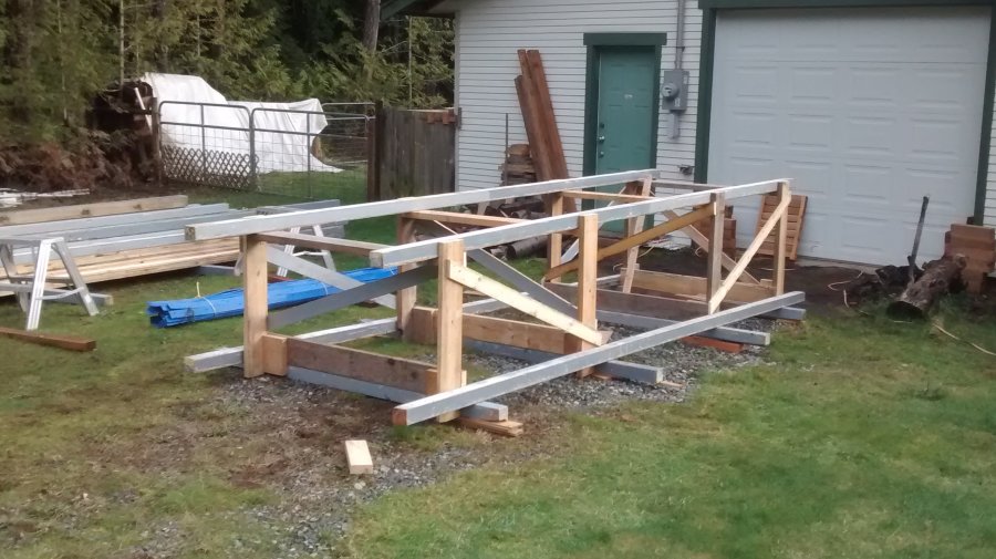
October 2017 - The rollover
Available Equipment
Massey Fergusson 230 w/ front end loader - weight about 9,000 lbs. Yanmar 240 - tractor only - weight about 2000 lbs. 1, 2 & 3 part blocks rated 4000 lbs. Weight of boat about 1800 lbs. (plywood - 700, frames - 400, keel - 700)
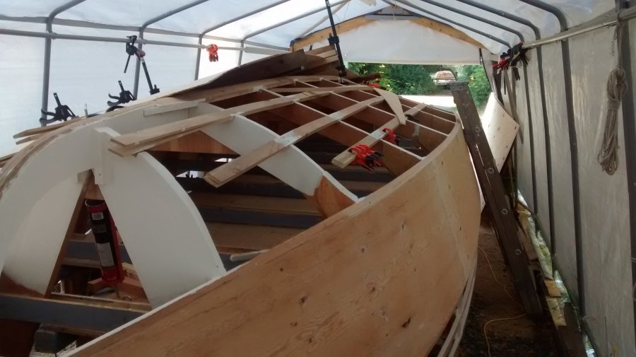
Hull Support
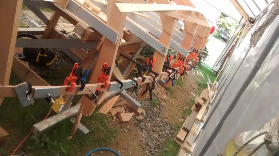
3 supports were constructed and positioned on frames 3, 5 and 7. Estimating that each support frame needed to carry about 600 lbs,, 2 - 2x6's were used. On the inside of the boat, 5 - 2x4's were fitted across the top of the frames 3 thru 7, also the construction table cross supports were left in place. As the roll starts, all weight would be on the 2x4 cross supports, about 360 lbs. per support or 180 lbs per each side of the frame (not including the construction table cross supports). The next segment of the roll would transfer the weight from the cap rail to the sheer clamp and chine log. The last segment of the roll would transfer weight to the chine log and the keel. Bracing was constructed only on one side and half the bottom
 .
.Braces were angled to keep the Center of Gravity (CG) between the ends of each brace. Each brace was double banded completely around the boat to distribute the forces as evenly as possible. The only place the braces contacted the boat where at the cap rail, chine log and keel.
Another problem presented itself right from the beginning of construction; the bow of the boat pointed into the workshop, so the whole boat needs turned 180° to get it on the trailer AND there is a power line to the workshop above the boat.
The

boat was jacked up about 1' off the construction table, supported, and the table removed. The tent shelter was pulled away, exposing the hull to the first light of day. The MF230 was brought in and ropes applied to see if the boat could be lifted with the tractor. Not only did it pick the weight up, there it was off the ground by at least a foot. The center brace was against the front bumper, front tires were a bit squished and the back of the tractor was really light. The 1800 lbs may be a bit under estimated.
The hull was pulled back and rotated 90° and put down on a nice level piece of ground.
First 1/4 of the roll

Re-positioning the ropes wrapped around the hull to lift the side fartherest away from the tractor, the roll was begun. The side was lifted, the tractor backed up, each in about 6" increments. When the tipping point was reached, the hull was supported and the ropes adjusted from a pull on the side, restrain the roll or push away from the tractor. By just backing up about a foot, the weight transferred and the roll continued until the side supports were flat on the ground. The weight was released from the tractor and the hull settled on the side with no tendency to flip either way. It was getting late, so the hull was secured in the side position for the night.
Second 1/4 of the roll
I has hoping to be able to position the bucket over top of the side past the cap rail and pull the hull toward the tractor and restrain the roll using the bucket with ropes around the bottom of the hull to the back of the bucket, well that was a good idea, just a few feet short in both directions. What was now needed was a way to hold the hull back once it got past the C of G. This is where the Yanmar 240 tractor comes into play with the block and tackle. The little tractor was anchored to a nearby tree and the block and tackle (6 part) ran between the tractor, over the top of the cap rail and around the hull tying it off to the cross braces on the bottom side cap rail. creating sort of a basket. Minimal tension was put on the restraint and the

hull was pulled over about 1 foot at a time playing out the block and tackle line until the tipping point was found. The hull was propped up, and the ropes on the bucket changed from pull to lift. The load on the block and tackle was taken off and the bucket now had the weight. There was nothing more to do but back up and lower the bucket until the supports were flat on the ground.
Loading the trailer

The boat trailer was now parked in front of the boat after the bow was dragged around another 30° or so until all things lined up. Without a bow eye, a large diameter rope was wrapped around the keel from the bow to the stern and back again. The bow was pulled up onto the trailer and the front and middle support frame removed since they were now off the ground. a pull with the winch on the trailer and backing the trailer under the boat went quite quickly. The last frame was removed and the boat pulled up to the winch. A path was cleared to the Quoncet and the boat moved under cover. For more pictures of the rollover, ( See Greg's Gallery here)
April 2017 - Ready to Roll??? - or what do I do with the boat when it's upright.
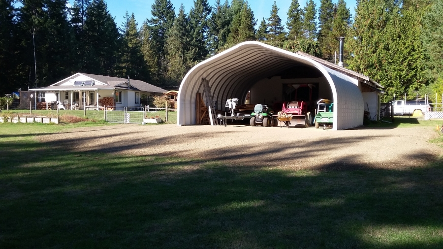
When I roll the boat over, the question came to mind "how do I protect the boat when it's right side up and on the trailer? A few measurements quickly concluded that the height of the bow when it is on the trailer is about 8" to 9' off the ground. That isn't going to fit under my existing cover and what do I do with the boat after it's completed. I used to just throw a large tarp over the boats I have owned in the past and they were good to go for the winter. That's not going to work for a boat with no superstructure, so need some more suitable for both the short term during construction, and the long term for winter storage. How about a Quonset hut shed attached to the back of the workshop. Who would have thought that project would take 6 months to complete
.
July-August 2016 - Keel build; drill shaft log
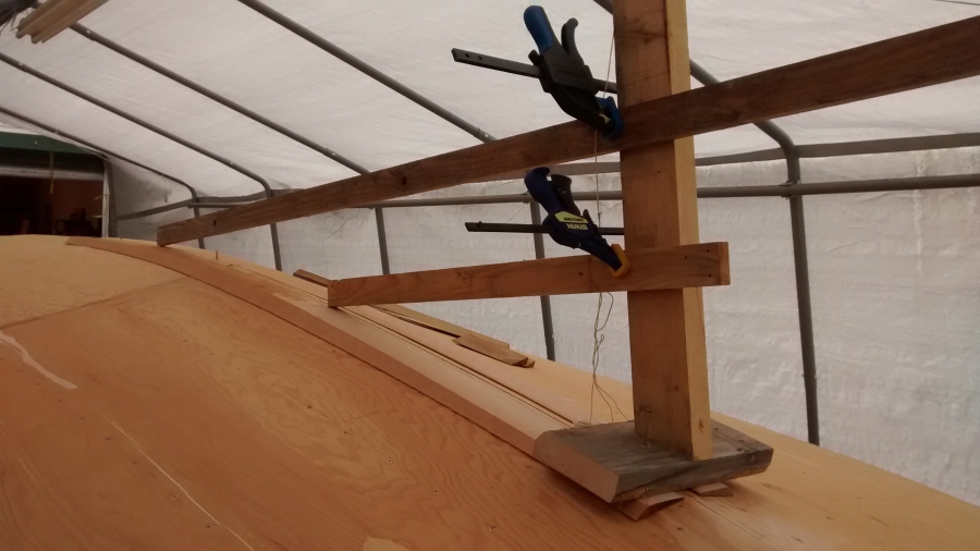
The bottom of the lower board is the center line of the shaft. Two cant strips were cut to produce a flat and horizontal surface and secured to the keel. The stern portion of the strips were fairly easy, but the angle of the hull quickly changes in the forward area so these needed to the secured first then leveled after. The shaft angle to the hull is 15°. A jig was constructed to guide a 2" drill into the keel. Additional blocking was placed on the inside to give the drill bit guide something to drill into and keep it straight. The guide was secured to the keel and the shaft hole drilled. To check everything out before things go too much astray, a shaft tube and the shaft was put in place and measurements confirmed.
The main part of the keel was laid up plank at a time and drilled, angle checked. 7 layers were completed along with a 4x6 stern bearing block. Four threaded rods were placed on the front and back of the bearing block. The remainder of the keel was completed with a total of 17 layers plus a 2x4" timber running the full length containing the keel bolts every 2 feet. This took time, glue and lots of screws, basically one layer every 2 to 3 days after preping the plank, gluing and screwing the plank in place (it's curved, so took a lot to pull a 1" piece of fir down tight). Took until mid September to complete the keel, by which time, the temperature was perfect to begin the fiberglass on the outside. 1 layer glass and 3 coats of resin finished by mid October.
June 2016 - Planking of bottom and sides complete
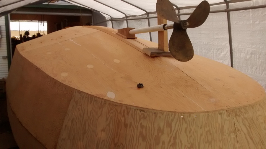
It been awhile since I updated the blog, but things have been progressing. The two layers of skin are now complete. Nothing really to report during this process other than I used a lot of tubes of glue and over 2,000 screws. I'm in the process of determining the position of the shaft log through

the keel. Got a board the length of the shaft, Determined where it ends at the rudder, know how far from the keel board it should be on the inside, located the spot at the stern where the end of the shaft should be, offset the shaft line by the amount from the center of the motor to the outside of the keel. Offset my board by that much at the stern and laid the board in and set the bow end on the keel line. I even build a mockup rudder to make sure where the end of the shaft should be.
October 2015 - Second Skin - Side Planking
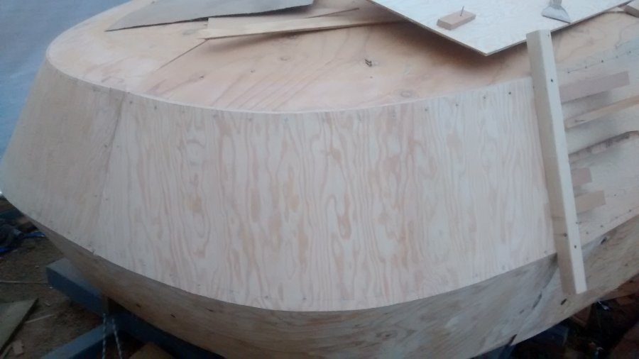
Well September was a bit of a bust, too much going on. Did some work on the Bulwarks and started the second layer of planking on the sides. Sternside planks cut cross grain on the plywood and bent around the curve sooooo... easy. Stern planking is as solid as a rock. Joints are butted on the second layer and well offset from the scarf joints on the inside layer.
Remember way back when the frames were being cut, there was a gold mine of wedges created. To avoid putting any extra holes through the plywood, a bridge was constructed using 2x2's for the vertical supports and some 1x2 for the h
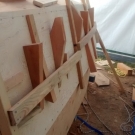
orizontal bridge members. The 2x2's are screwed to the chine and sheer logs using 2½" screws in the same holes as the planking uses around the perimeter. The 1x2's are fastened to the 2x2's with 1½" screws. When the sheet is in its final position after gluing, the 2x2's are put on by removing the perimeter screws. Wedges are pushed in between the bridge and the planking and all becomes tight.
August 2015 - Bottom Planking
Bottom Planking
-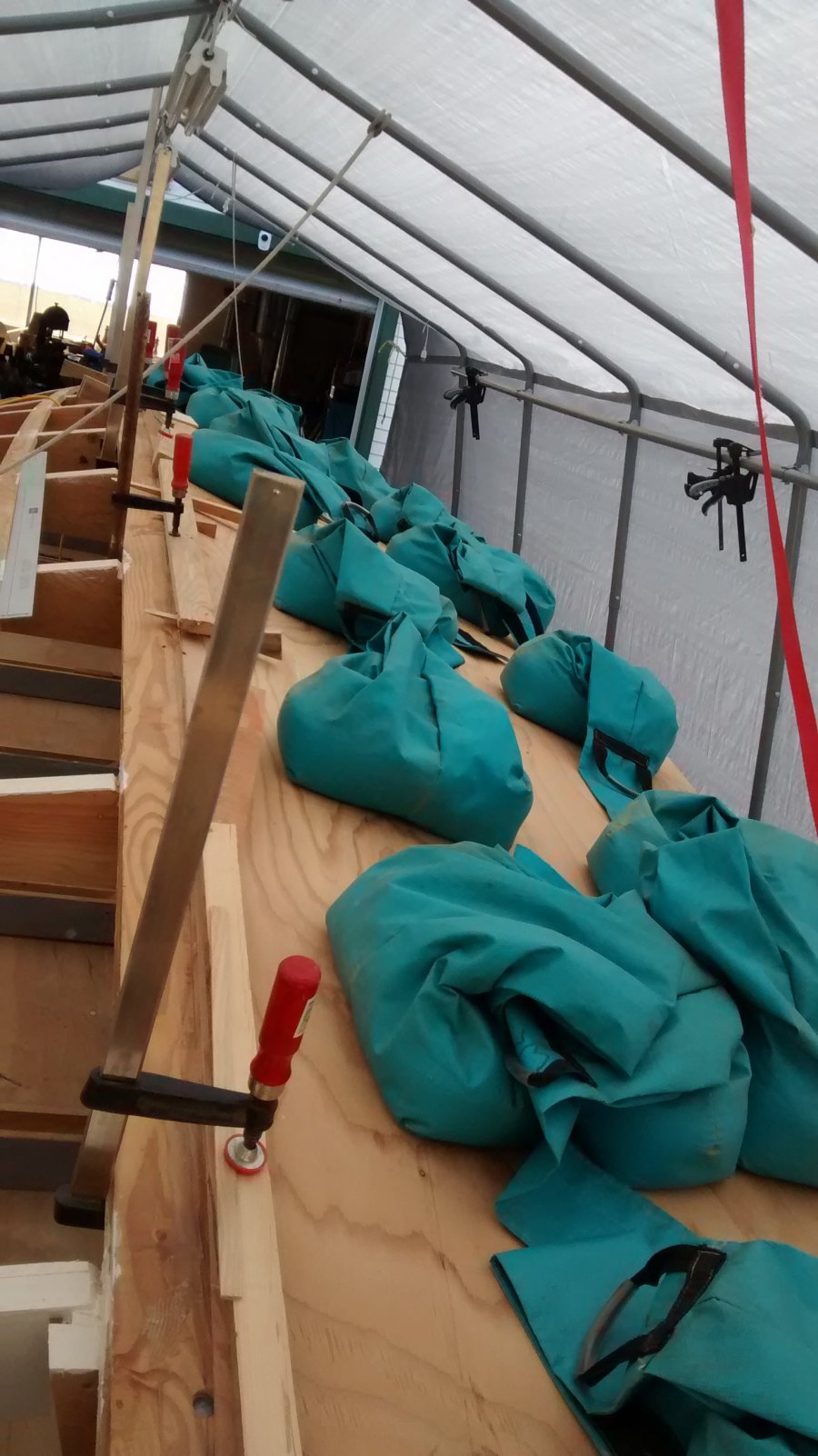
Port half of bottom plywood now glued into position and held against battens using 20 tunnel weights (dog agility stuff), each about 40 lbs.. for about 800 lbs of weight, lots of bar clamps to reach over the keel and a hand full of blocks screwed to the chine and keel to pull the panel into position. Waited until the temperature was quite cool 12°C in the morning to give me lots of time to get the glue down, position the plywood, and get some screws and clamps in place. The ends of the forward battens had to be pushed from the underside against the plywood. Front half done first, keeping the back half in position with screws and blocks at 3 points so the panel would not shift from its position while being lifted up on the other half to get the glue down and spread.
July 2015 - Scarfing Plywood, Painting the frames, Planking the sides
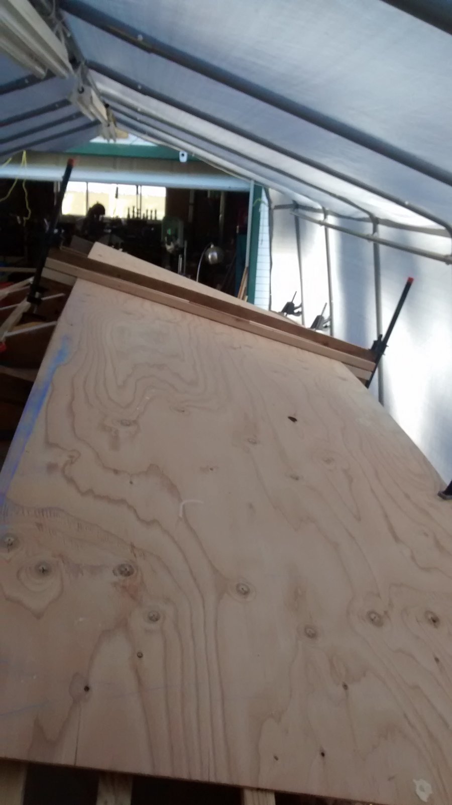
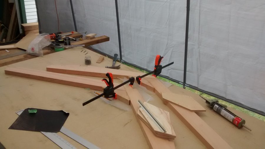
Doing the scarf joints for the bottom panel in situ on the bottom didn't appear too practical because of the 4' width, so laid the sheets out on the bottom of the boat and made a clamp 5' long and 2½" wide 1½" thick with a backing that bowed the board on edge along the back with a spacer in the center that bowed the board. Set everything up off the bottom of the boat and glued the bottom sheets end to end for a panel 23' 8" long (2 scarf joints 2") Now I have a single sheet for the bottom. Picture does not show the detail of the clamp, but other pictures in the gallery should give you an idea. Next step is to scribe the keel line, and the chine line then trim oversize along the chine at the bow to do the fitting into the butt joint where it meets the side.
Installing the side planking - Side panels were cut to approximate size, scarfed, and installed individually. Process seemed to work okay. Needed to back the scarf joints and wedge behind the joint for a nice tight fit. Planed and sanded the chine for a nice flush fit. The sheer line was trimmed and sanded before gluing. Alignment was maintained using screws at each corner of the panel. A simple scribbling block was used to scribe the center line of the sheer. Work is progressing, but not as visual as the framing. Lots of steps before the panel can be glued in place. The transition point where the bottom panel goes from flat to vertical at the bow was made ahead of frame 7. Not sure how this is going to play out, but needed to pick a point where to stop sanding the top of the chine. A similar transition point happens on the sheer side at the stern where the bulwark turns around the stern harpin.
Scarfing Plywood - Modifying the scarfing jig wasn't practical, so a new design for scarfing plywood was made. Looked at the saw method, didn't have a blade big enough to cover 2", and didn't like the idea of taking off the guard and putting on an 8" blade. Tried the planer with a cradle to create the scarf, but that just shredded the wood, very messy. Next thing was to use the router. Lots of samples on youtube, so tried to take parts that I could use and make my own jig, that didn't work too well either. Couldn't get the plywood to lay flat so scarf was a bit wavy. Clamped the plywood down hard to the bench with the edge just at the edge of the bench and used the planer to rough out the angle, then finished it with a belt sander. A bit tedious, but satisfactory joint. Used this technique to make some scarfs on the stern panel in place. Since the panel was so curved after forming it for a week with hot water and lots of clamps, there was no practical way to work with the panel on a bench. Scarfs came out some of the best I have done so far. Painting the frames - Primed and painted all the areas that would be unaccessible once the skin was put on. Two coats of primer and one coat of finish; places like frame edges, glue blocks, tight corners, and anything that one would have to stand on their head once the boat is righted. Everything that you can see will soon be upside down in a few months, so like they say in in Army, if it doesn't move, paint it.
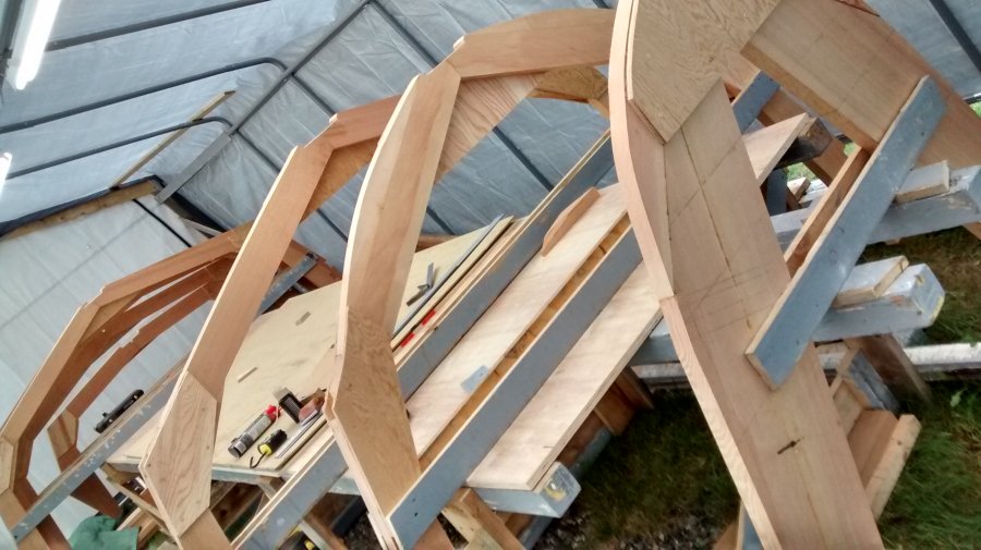
June 2015 - Deck Beams, Battens, Fairing
Battens
- After reading through Doug Harrison's experiences with his battens, I was very quick to realize that these were going to be an interesting installation. With the use o
f reclaimed fir, and the experiences with the chine log, bending and twisting the battens around frame 8 & 9 was going to be difficult. Soaking the ends of the battens for 3 days with towels and hot water would not allow enough flex to make the battens fit. With the amount of force I was putting into the twist, something was going to give. Reading chapter 17 (pages 151 - 155), specifically page 151, of Glen-L's
Boatbuilding with Plywoodbook, a decision was made to kerf the batten. As luck would have it, the top of the supports for the frames on the building frame just happened to be ¾" higher than the deck of the band saw. This made it fairly easy to support the 20' length of batten while cutting the kerf. I put the thinnest blade I could find on the saw (.030") and split the thickness in half. It should be noted here that the battens should NOT be fastened to the forward frames and should be left to "run wild".
After the battens were installed in their notches on the frames, shimming was required on frame 7 battens to get fair lines. This was caused by the increase in radius on frames 8 & 9. Lesson here, check the fair of the battens before cutting any notches, shim accordingly, then cut the depth of the notches to maintain a minimum ⅛" proud of the frame. Some are now ⅜" proud, but the line is fair. The picture right shows the deflection of the batten after the kerf was made. It does not show the 30° twist that is also in the batten. Check out the
gallery, there are lots more pictures trying to depict how the end result looks. Prior to putting in the kerf, the batten could not be bent below the line of the top of frame 9. The Starboard side is going much easier now that I know what depth each of the notches are.
Fairing
- The ancient art of taking a piece of very expensive wood and turning it into sawdust and a nautical term from the 17th century. The past two weeks have been spent roughing out the lines on the logs and keel using a saw kerf cut in above the final angle, then rasping in the Rabl no
tches to the finished dimensions. Plywood was ordered last week and should be arriving in town the coming week. The whole exercise takes time trying to avoid over planing and sanding. The notes talk about a disc sander, I've opted for a power hand planer, and a belt sander with 40 grit paper. The finished height of the keel and chine log is ⅛" above the level of the frame at the ends (some are curved). As noted in the notes, these frames are "floating frames" not attached directly to the skin, only to the longitudinal members and the stem. This is making the fairing fairly easy (relatively). Waiting for the plywood so I can finish fairing the stem and the sheer around frame #9. Found a piece of ¼" paneling from the neighbour so I can fair some of the bow angles. Need to take out some of the wood of frames #8 & #9 that I put in to increase the radius of the curve, not much but holding the panel out from the line of the battens.
Deck Beams - carefully cut out the camber board, marked all the half widths, took the board out to the boat and slowly realized that there were only two frames accessible through the building frame from one side to the other. Also realized that it might be wise not to put anything on the inside as this might cause a few problems when it comes time to turn the boat over.
May 2015 - Keel, Sheer Clamp and Chine Logs
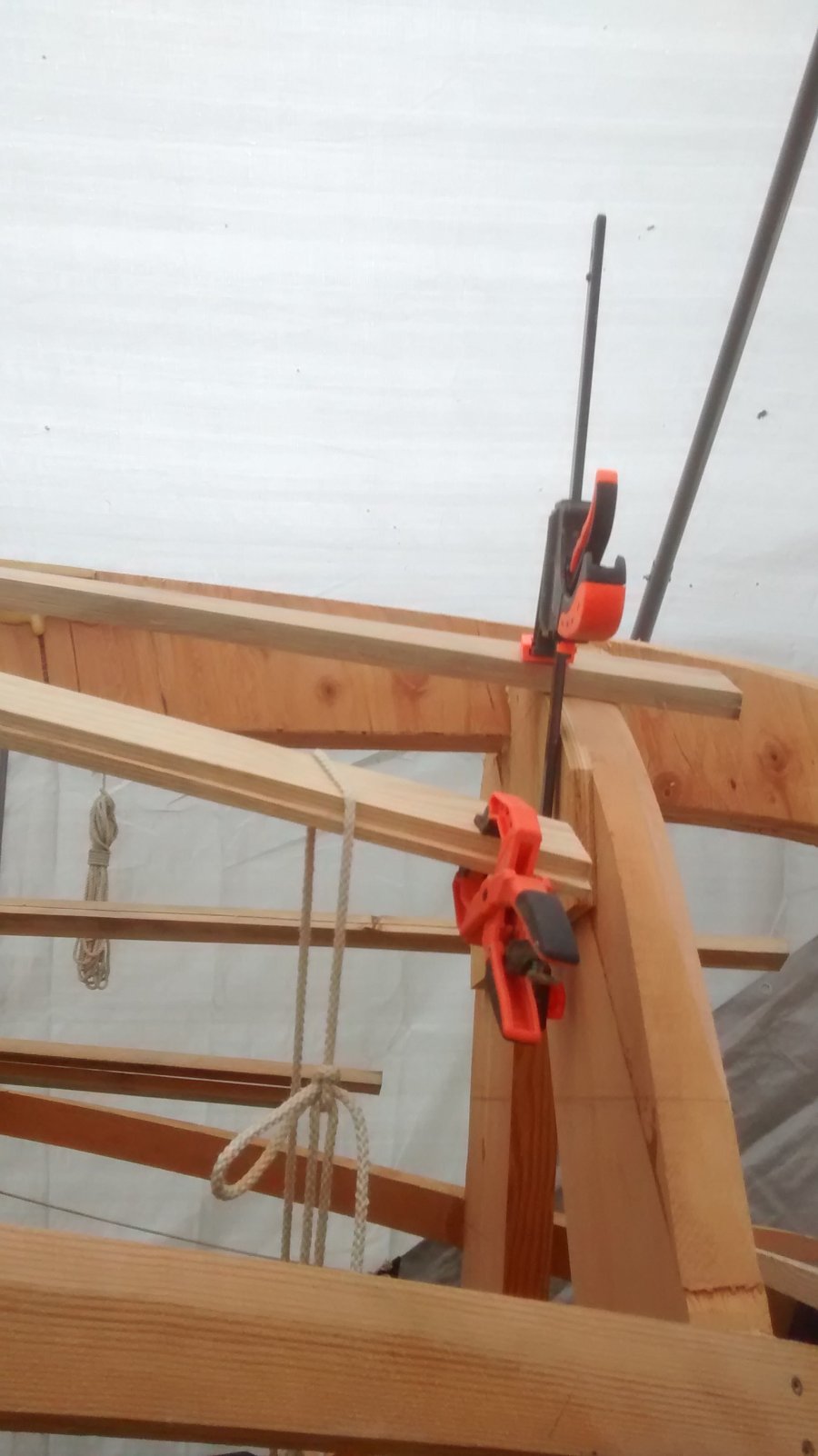
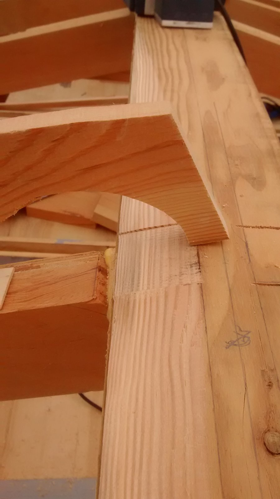
Deck Clamps & Cap Rail have resulted in a major design decision. The drawings show the deck clamp and cap rail going from frame #1 to the stem post more or less suspended in thin air while making a 90° turn in abo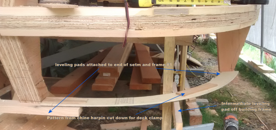
ut 4' of distance. First question I had was "how to make both sides the same while confo
rming to the curve of the sheer harpin?" After going through Doug Harrison's pictures, it became apparent that some form of bracing was needed.
(See Doug's intermediate bracing)
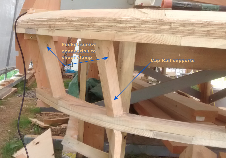
Doug installed 3 intermediate "frames" to bend the deck and cap rail around on each side. I set up some temporary braces mounted off the building frame and tried to make the bend. This wasn't going to be easy. Soaked the wood for a day and gave it another try, again no success and a lot of strain of the wood and the shape was not going to match the sheer clamp that well. At some point, I compared the chine harpin to the sheer harpin and thought, why not duplicate the cap rail the same way as the chine by constructing a harpin. Studied all the books, poured over the drawings, and could see no compelling reason not to go with a cap rail (bulwark) harpin from frame #1 to the stem post. A harpin will provide substance to bend the plywood skin around, a good surface to attach the plywood, a consistent contour and curve matching the sheer, and a good surface for the deck surface. Next issue was how to support the cap rail harpin. Decided on vertical braces between the sheer and cap rail. Used a pocket screw into the sheer so there was no screws on the outside face to interfere with faring. Put 3 braces in on each side. Set the cap rail into frame #1. Lines look good so far.
Sheer Clamps
are progressing a lot easier than the Chine Logs. With the footage of ⅜ x 2¼" material needed, a lot of scarf joints were made.
When laying up the layers, don't cut anything off the length. Let it overhang the harpin notch. This will give some wiggle room when squaring up the sheer to stem angle, and can be cut just before gluing the piece in place. As you cut and adjust the angle of the sheer to the stem, the individual layers can be moved up to make the perfect fit. One layer at a time was installed, the first layer, glued and screwed (with 2 screws) to the frames. The second layer glued to the first, then 1 screw put in the middle of the board to the frame. The clamping needs as many clamps as you can muster. More than 50 clamps were put into service. Every time there was a sale on clamps, it was worth the trip to get as many as there was on the shelf. The third layer was a glue up only, no screws. Always work from the stem to the stern. When half way down the side, check that the layer hasn't crept away from the stem. Work has been done early in the morning so the glue doesn't set too fast, this give an opportunity for undoing the clamps and moving the layer back into position. The breasthook was prepared but only one of the two was installed. After the sheer clamp was complete, the second layer of the breasthook was installed. There was minimal stress on the sheer to stem connection compared to the chine .
Chine logs
also needed scarf joints. Put the joints near the stern. First attempt to pull the logs on each side to the stem resulted in one breaking (port side). Break occurred at a small tight knot in the wood, not at the scarf joint. The log is posing a real challenge, starboard side log also broke, and that was after it was in place for a day. Both logs broke between frames #7 & #8 Only a variation in the grain, no knots. Wood used is salvaged fine grain fir, very dry and quite old. Wrapped the new logs in towels and used the hot water treatment for 3 days pulling the log into place a little bit at a time. Let it sit for another day with the towels on, then removed the towels and left it for yet another day. Still a lot of tension in the wood, but everything seems to be settling down. Needed additional bracing on frame #9 to keep it square while pulling the log into place. With so much tension on the chine logs, I installed a bit of a breasthook to take some of the strain off the joint between the stem and the chines.
Check the gallery pictures
.On completion of the chine log, a plywood bresthook was fitted and the existing support was included in the support. This was glued and screwed in place.
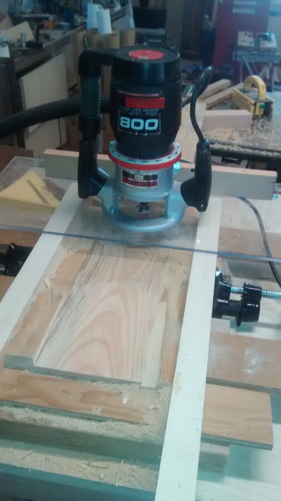
Keel created the challenge of doing a scarf joint. Lots of info on the Glen-L site and YouTube. Needed a jig that would accommodate the router I had. Found a 1" mortising bit with a guide bearing, but this didn't really work. Finally settled on using sacrificial boards on each side of the board being scarfed. Took a couple of tries to get things level and square. Angle made for a 12:1 scarf. Make sure you put a vacuum behind the router to catch-all the chips or you will have a real mess to clean up. Second layer of keel added after the chine logs done, mainly due to the fact that I was using a lot of the clamps I needed while making and setting up the chine logs. Again found the pre-notched slots for the keel needed to be filled back in with angle wedges. Only one side of the notch was correct. Putting the limber hole in the middle might have some value toward the stern, but the side limbers should be more than adequate. If the battens are to be proud of the frames, then the limbers may be redundant.
Scarfing jig example from Glen-L forum JIG
Jig for plywood scarf using router - Plywood JIG
April 2015 - Stem & Stern Posts, Harpins

Stern post in position with sheer and chine harpins in position. Layout for harpins done using an antenna from a ham radio bent around the arc from the stern to frame 2 and traced on to a sheet of ¼" underlay fiber board. (see photos in the gallery). A mistake made at the stern post by not offsetting it 3" away from the stern post. The line from frame 1 and 2 is on the outside of the curve, the line from frame 1 to the stern post goes from the outside to the inside of the harpin. This caused a few problems, but not a show stopper (yet). Will need to add to the outside of frame #1 to fill the gap. At the least, everything is still symmetrical about the center line. Creating the harpins was not complicated, but more an exercise in using the bandsaw and belt sander to smooth out the curves. Cutting the chine notch in frame #1 was another story. Trying to hold this piece of timber in the correct position over the top of frame #1 to get the angle took a bit of doing and lots of blocks and clamps. Same with the sheer harpin to get the angles, except had to position the timber to the outside of the frame.
Cutting the notch for the chine and sheer logs required a bit more thought. Since there was a notch in the end of frame #2 already, it was then I realized that there needed to be an angled notch. At this point, I needed to cut a wedge to fill the notches back in at the correct angle, or at least a better angle based on a straight line between frame #2 & #3. Using the same straight line, I was able to extend the line and the angle into the harpin.
Stem post cut from pattern, 2" added to bottom end of post to get the 2'2" frame spacing. Notch in frame #9 took a bit of study to determine the depth. Used the DWL to the inside of the post distance 10" to set the depth of the notch.

Also added 7½" to the top of the post which I'll shape round for a cleat or bollard. Slope of ground is perfect for the added length. Used an oscillating saw to cut the bottom of the stem notch and worked very well producing a smooth, flat surface with no chisel or rasp work.
Building frame needed extensions added to accommodate the extra length. Added to both ends to provide support for frame #9 and frame #1 and the stern post. Cut the stern post in straight lines, no curves.
(editor: See Greg's Gallery here)
March 2015 Frames
The frame construction is well under way. Each frame's assembly was a wee bit different than the previous as I learn how to assemble the frame and glue things together in sequence and keep my hands somewhat clean while doing so. Temperature running around 10°C, so not too much in a hurry to do things until after lunch. The construction frame is working great for putting the frames together. A sheet of flooring underlay is perfect as a layout board.
For the layout, make sure that you have the DWL and the CL EXACTLY in the correct position on the board. It makes life really easy to double check the position of the key points on each frame. The coloured pencils are perfect for figuring out what line is what on the board. I lay the pattern I did on the butcher paper out on the underlay, drive a small finishing nail through the key points of the frame, identify the points on the underlay, join the points with coloured pencils, lay the frame members out on the underlay and start the assembly knowing that all the members are symmetrical, and in the correct position without damaging the drawings with glue. A piece of wax paper under the frame member joints works great by keeping the glue from bonding to the underlay.
May post - New lesson learned after putting in the chine log. DON'T CUT THE NOTCHES FOR THE LOGS OR THE KEEL, Mark them well on both sides of the frame, one side is correct, the other is too deep into the frame. Put in all the lines you can think of, center lines, mid points, anything that can be used as a reference when the frame is sitting on the building frame. Make sure you have the DWL on both sides of the frames. most of the notches are tapered, not square. Notches are quite easy to cut after the frames are in position using an oscillating saw.
I did find that putting a 3" screw into the center of the chine notch to the bottom frame works well to pull the side frame into the bottom frame and keep it's position accurate. Pre-drilled the hole and over drilled the top part of the screw hole to allow the screw to pull tight into the bottom frame. This shouldn't interfere with any fairing needed to put the chine log in. If it does, there is no problem removing the screw Added a knee brace to the inside of the gusset to fill out the gusset and add some strength to the corner joint. Electronic protractor very useful for this, gives the angle to the nearest 1/10°. I glued and clamped the knee into position before the gusset applied. This wasn't called for on the drawings, BUT, I saw all this nice wood on the floor of the workshop and figured it was worth the effort to make the knees and salvage some of the wood from the scrap pile and filled out the gusset for added strength.
October post - Save anything that looks like a wedge when cutting the frames. These are very handy to press the second layer of the plywood to the inner layer.
Things learned; laminating glue used on the frames, Titebond III; glue on the joints and gussets Lepages PL Polyurethane, totally waterproof and works well, abet a bit gooey at the cool temperatures, but spreads well: don't run the screws in too fast. Give the glue a bit of time to move. Once it's set, the wood will break before the glue fails. Use a dab of the glue to lube the screws while running them into the wood (keeps them from breaking).
It's the end of the month now, and I have all the frames complete. I realized that the building form will have to also be a scaffold so I can put the keel and battens in and fair the keel. I've installed a couple of sheets of 3/4 ply on top of the building frame so I can stand on it while doing the work. Nice thing about the plywood; it's square and checked by building frame squareness. Still have to do the stem and stern posts, so there is still time to use the building frame as a work table. I'll run a line down the middle of the plywood for the frame alignment. Can't think of any particular reason why this could be a disaster looking for a place to happen: beats standing on air while working the keel and the battens.
Picture here shows the plywood on the building frame with the frames in position for the keel and logs, but that's getting ahead of myself at this point. Just wanted to see how it would work out. Most valuable tools for this part of the project - thickness planer, jointer, 14" band saw with 3/8 blade, belt sander, cordless drill and impact screwdriver. Based on Doug H's experience with his boat, I've redone the arc on the bottom frame to increase the radius and get a better fit with the plywood. At the least, I'll have lots of wood to do the fairing.
Note from May's blog entry: START SHOPPING FOR CLAMPS 2½" C minimum. Eventually, you should get at least 50 clamps. C-clamps are best, the ratcheting are okay, but can't pull like the C-clamp. Borrow from your neighbours, hit the garage sales, the more the merrier.
Check the gallery as there is lots more pictures of the work in progress
Next step - Stem and Stern posts, harpins
(editor: See Greg's Gallery here)
February 2015 Intro & Construction Frame
My name is Greg Rehill, I live in Parksville BC, Canada, on the coast of the Georgia Strait, which separates Vancouver Island from the Mainland of the rest of Canada. I retired here in 2006 and have been enjoying many of the pleasures of the Island. My son (a marine engineer) and I bought a Bayliner and enjoyed cruising the area. A nice boat, Volvo diesel, and was fun while the marriage lasted (not me, the son's). So the boat was history. I've been involved with the Canadian Power Squadron for lots of years, instructed, commander, even got my celestial navigation, but still get lost in the parking lots. I've cruised Desolation Sound, the Georgia Strait, and all the waters from Portland to Campbell River. In the good ol' days I cruised the Arrow Lakes and the Kootenay Lakes in BC. My parents always took to the waters, retiring in the Okanagan Valley, they enjoyed Okanagan lake and all the fishing lakes in the area in a 26' PLYWOOD cruiser powered with a 125hp merc, the biggest in its day. I'm just guessing here, but looking through the designs from Glen-L, looked a lot like the Vera Cruise.
So............ this old Seadog here has decided to tackle the project of building a boat. I've built cabinetry, houses, done wood turning, made lots of things out of wood, but nothing like a boat.

This started about a year ago, the idea grew and I studied lots of plans. Then while surfing the net I found a 27hp Yanmar for sale. Someone once told me, if you are going to build a boat, get the motor and build the boat around it. Now I have the motor, about 1500 hrs on it, needs some TLC, but it runs, and as diesels go, it sounds sweet, a bit rough on the idle, but purrrrrs at 1200 (no load, no smoke).
My first effort in finding wood for the frames came with a surprise. About 1km from our house is a small sawmill which does custom cutting. I found the place, but it was raining so hard I thought I would come back later as no one appeared to be working in the yard. I was given the name of the place by a timber frame contractor and an individual who makes custom outdoor furniture. The place is called BeaufortTimber Products in Errington BC (actually that is where I live, but the mailing address is Parksville). I went back a week later and there was life in the yard. I asked the first person I came upon about wood for building a boat. WELL, little did I know, this little sawmill provides timber for boatyards all over North America. He quoted Lunenburg NS, Florida, and a whole list of other boat yards. Then he led me to a wood pile of old growth Douglas Fir with all the exact dimensions that I would need and said pick what you need and the rest is history for the Titian tug.
After building the construction frame, I've assembled one of those garage in a box frames over the frame. First problem here was "it was too short", so we added another wood built frame and instead of the out of the box cover I got a long and just the right width tarp to make the cover. Now we have a 30' boat shed, 12' wide and a well drained base and a driveway angle. The whole thing is anchored down with timbers from the dividers from between the sheets of a curling rink. (16' long fine grain DF) with a lot of holes and nails in the wood. I'm looking for a metal detector and should be able to strip off some 1" to 1 1/4" x 4" strips if I'm lucky.
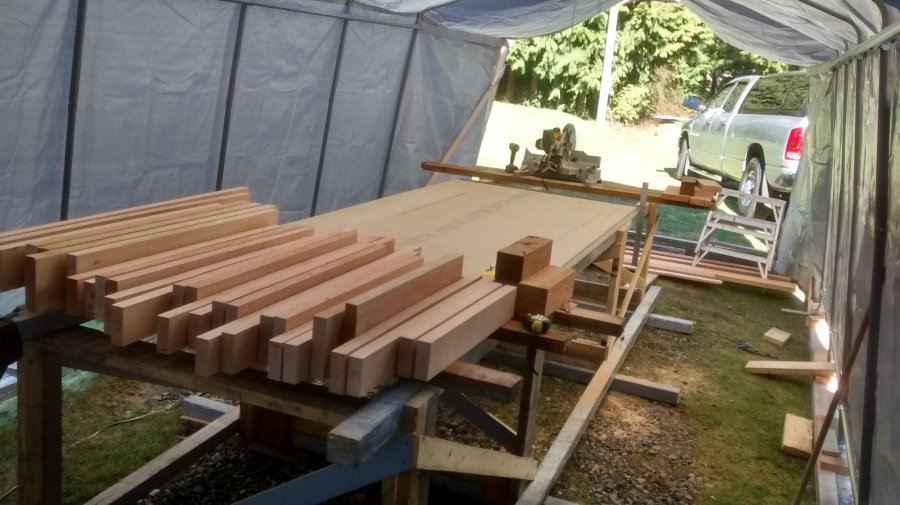
The building frame is now being used as a drafting table to make patterns using the full size layout sheets from the design. I was getting a bit nervous about the layout, so I found a roll of butcher paper and did full scale drawings of the individual pieces using the drawings. A well worth it effort as I learned a lot about the design as I did the parts of the frame. Now for the next week or so, I will be cutting and putting together the frames.
(editor: See Greg's Gallery here)