
Metal Boatbuilding Notes
Posted by Kevin Morin on Dec 4th 2015
Since the topic of building in welded aluminum has seen a few recent posts, a little awakening from this category's sleepy past, I thought I'd write a series of articles on some of the aspects of metal boat building that seem to be challenging to new builders. I'm not sure these topics 'scare' everyone but more than a few emails to me indicate that potential builders consider their lack of knowledge too big an obstacle to overcome.
As a result of this seemingly widespread lack of understanding about metal boat building techniques I've decided to post a series of illustrated articles that lead to a wider (maybe better?) awareness of "how to" build a welded aluminum boat. I will NOT be (fully) addressing welding in this initial series as I consider that another issue and one you may be able to find instruction for at your local community college or tech training center? I will concentrate on, some fixtures, tools and ideas for "fitting", a few basic methods of working with sheet material, and especially on 'taking off' developed sheet outlines from a frame - model size or full size.
This series will not fully discuss the NC cut packages where the frames, (some) longs and hull panels' outlines are already laid out by computer and cut - ready for assembly into a boat. This thread will concentrate on the 'old school' method of doing all the layout and fairing, all the cutting and all the tack up (but not discussing welds in detail) by hand with hand tools (powered hand tools!).
My goal is to add to the Glen-L 'knowledge base' of reference articles in the library here. The reason to post here is the community of owner/builders who may build one or two boats and use them for themselves and their families- a boat building community that I wholly support and admire. If I can help someone to learn a few steps in the building process that will make their boatbuilding easier or results in less efforts while contributing to a higher quality final boat? Then I've accomplished my goal and the effort to post was worthwhile.
I'll start with some remarks about building and the age related limitations and considerations I've learned as I've gone from the bullet-proof 20 year old welder to the senior citizen (65) builder who needs to pay more attention to "gravity".
Please feel free to join in, this is not intended as the last word, just a series of explanations of the questions and problems I've received in emails for years. I believe most if not all the general ideas here will be seen by the wood working boat builders as same or very similar methods?
Let's start with some basic ideas; terminology.
In order to make a series of posts that have any hope of giving the readers some ideas that may help in a welded metal boat project, experience shows that giving some terminology or definitions should be the first step. If I use a term, and you read it for a definition I don't intend; I'll have written a statement you won't understand as I've intended- so I'll have sown confusion. Confusion is what I'm trying to reduce!
So here are some terms and remarks about the ideas that will be presented on this thread. Definitions and background information that I think need to be the 'given facts' we all use when reading this series of posts. IF you know I'm wrong, of even think my ideas should be edited- NOW is the time to add your post and correction! If I'm telling the Forum something and you've seen that is incorrect PLEASE take the time to call it out, so we can all move toward better knowledge of welded aluminum boat building. Thanks, KM.
Welded aluminum boats are boats made of Marine Alloys (of Aluminum), usually 50XX and 60XX series alloys and are not formed of the other series alloys like: Gregors, Lunds, Starcrafts, and other stretch or roll formed and riveted production boats. The manufactured boat is made of aluminum but is not realistic for home building due to the huge investment in forming equipment, fixtures and engineering costs that are required. Welded aluminum boats can be made one-off with wood working shop tools and a DC MIG welding power supply, using adapted wood working techniques and welding.
Link to a vendor's site: http://www.alascop.com/al.php
Welded aluminum boats are those boats made of Marine Alloys and cut by hand or machine where the individual structural elements are cut out from various metal stock, joined by welding, MIG or TIG and not by riveting of the main hull seams; chines, sheer, keel and transverse elements. Click here for the difference between MIG and TIG welding.
Metal terminology; uniform thickness plates or sheets of marine aluminum are available in different overall sizes but the term sheet begins at 0.125” or 1/8” material thickness and is commonly used for relatively thinner material. Plate is the term used for material thicker than sheet, so; 0.160” or 5/32” material, 0.187” or3/16; 0.250” or ¼”; 0.375” or 3/8” and thicker- are generally referred to as plate.
Aluminum can be forced through a shaped “die” to result in a continuous length of that shape’s outline; this process is called extruding and means that aluminum, unlike most other metals, can be purchased in an almost endless number of cross sections. This group of aluminum stock is generally referred to as extrusions and named by the cross section, for example; extruded angle, extruded channel or extruded T bar. Shortly after working in these alloy shaped length the word 'extrusion' is dropped and they are simply, angle, channel and Tbar. Most boats can be designed and built of a fairly limited number of different extrusions combined with plate or sheet material. Because extrusions are sold in many shapes and many different sizes of those shapes, the variety of extrusions commonly available is very high.
Vendor link: http://www.alascop.com/al_rbs.phpWeld aluminum boats are most often made from two series of aluminum alloys the 5000 series and 6000 series which have good welding characteristics and good corrosion resistance to salt water. Once welded, both alloy series do lose some strength in the weld zones (HAZ Heat Affected Zone) but overall; retain enough strength to allow high speed, lightweight and reliable welded structures.
Design and Layout Terms: Curves are lines that are not straight and in boat terms we call pleasing curves ‘fair’ and unpleasing curves hogged. If a curve has no angle points, or kinks, (hoggs) or is not curved in a manner UNpleasing to the eye in different locations along the curve, the curve is fair.
For a welded boat hull (like most hulls of all materials) to remain fair, the shapes of the hull must all be described by either straight lines or fair curves. In boats, we strive to design and build in fair curves more often that straight lines. Many boat curves are in 3D space not flat lines found on a drawing- these lines curve in more than one flat plane in space.
Battens are drawing tools used to draw curves, and especially to draw fair curves. Battens can be any semi-rigid material that bends uniformly without permanently distorting and therefore relaxes back to a more or less straight line form when released from clamping forces. If you hold a 6’ shop ruler, on edged, into a curved shape, it will remain fair until you exceed the curvature of that ruler’s elasticity; then it will deform/bend permanently and not spring back. Boat building battens should always spring back or they have deformed. IF you select a metal batten and it deforms in the curve drawing purpose; that batten should have less cross section and the work should be redone.
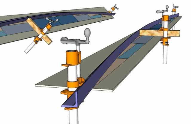
This image above shows a (purple) angle extrusion being used as a batten, held in place by three clamps (more are commonly used) to layout a line that is an expanded circle; camber pattern that would be common for deck beams. The angle is uniform in cross section, stiff enough to bend but not deform and rigid enough to make the arc an even and fair curve; therefore this extrusion qualifies as a batten for this layout job. Typically all lines in any boat can be drawn with off the shelf extrusions resulting in measuring, marking and cutting then fairing the edges of parts of a boat to within 1/64th Inch- by hand with no special tools. However, this method does require time to perform the layout, marking and hand cutting and clean up; all of which can be hired out by purchasing a Cut Files package and having this work done by an NC cutting service.
IF a wooden batten exceeds its elastic bending capacity, it will snap but metal battens will simply bend and deform into the bent shape. Our discussion will not focus on hard shaped drafting tools like French Curves, Ships' Curves or other rigid outline drawing tools.
(Welded Alum.) Metal boat hulls are of GENERALLY two types; one much more commonly used than the other. The first type in our discussion is a series of hull shapes that are the combination of three exclusive geometric shapes: flat planes, conic surfaces, or cylindrical surfaces where all the boat’s shapes in the entire hull are drawn from these three basic shapes. These hulls are called developable shapes where all the surfaces can be cut as outlines of flat material and then pulled, cold formed, distorted without Plastic Deformation into the hulls' forms. All that is required is to cut the outline and hold the material to the frames OR to hold the materials outlined edges to an adjacent sheet surface outline piece.
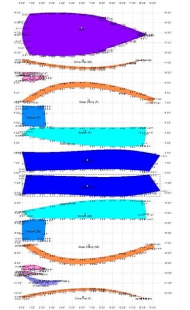
This shows the marine software output of all the hull panels of a little skiff as flat outlines- these are the 'developed' shapes as they would be cut by an NC service.
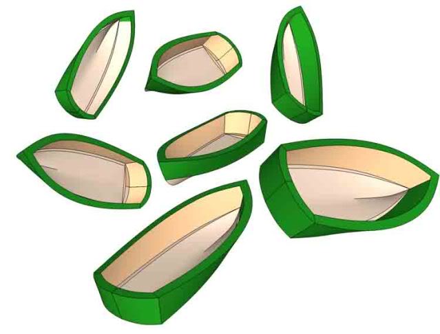
This image (above) shows the 14' skiff from various angles of orientation and scale. Some of the hull panels may look like compound curves but they are not. Some hulls' perspective drawings or models may give the illusion of compound curvature even when the hull is fully "developable".
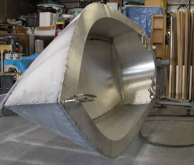
(Above) the same 14' skiff outlines of all hull sheets cut and tacked edge to edge showing the relative accuracy of computer generated cuts. This hull was laid out and cut by hand using the outline's dimensions- the method in this series will result in this level of accuracy if applied carefully.
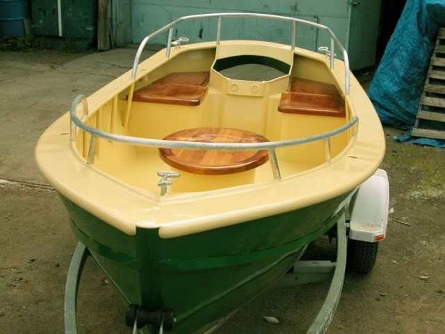
(Above) The 14'er finished and painted with the hatch cover/seats. This is an example of a developable hull, all flat shapes, cut to outlines and then fit and tacked edge-to-edge using methods that will be show in following posts.
NOTE: I am not selling plans, do not offer any plans or cut file packages, and do not offer to consult or help build any of my designs. The illustrations here are my own, the pictures generally of my work, unless noted, and are exclusively here for education and explanation of the processes I went through to build the boats shown.
The second, and less common welded aluminum boat designs have compound curves, where the sheet materials have been deformed in thickness to stretch to form geometric surfaces not limited to the three of the previous limited surface type hulls. These hulls need some of the hull's plates or surfaces deformed by Plastic Deformation using English Wheels, or other types of stretch forming equipment.
Flam is the term used for the “lean out” topsides of a conventional hull and Flair is the term used to describe the less common hull’s topsides shape. Flam is a combination of a cone and cylinder which can be formed of developable surfaces without any roll forming or stretch forming. Flair is a shape that requires forming and in most cases would also require planking or piecing the surface together from multiple formed pieces of plate or sheet.
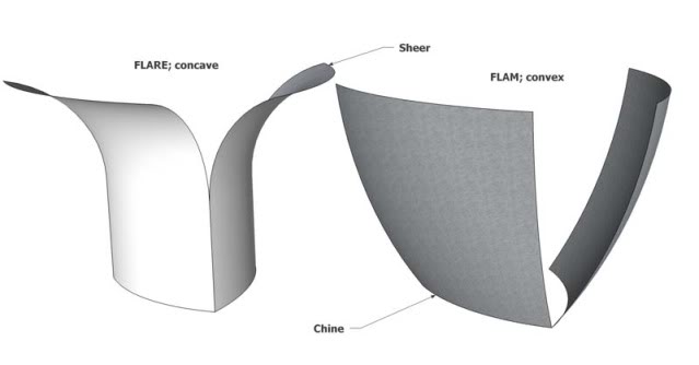
The image above shows the two terms we'll see in the future... Flam and Flair. Lots of owners say that flam is flair, but what then is flair? I show the difference in this illustration and suggest that most all designs for the home builder only involve Flam? Flair requires the metal to be shaped in two different directions. So take a piece of paper and hold it into a curved boat side and then peel the upper edge outward! the paper will tear and you'll see what Flair requires.
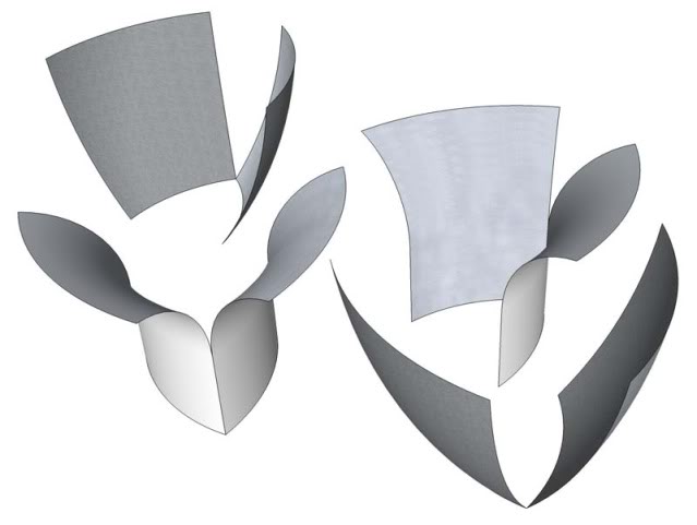
(Above) the same idea just with more views to make the geometry easier to see in a typical all gray online illustration. The Flam shape, even with some bulge (convexity/bulge from chine to sheer, outward curvature in the topsides) can be formed from developed plate shapes in welded aluminum but.... the Flair will require forming equipment, may require multiple planks instead of one large 5'x25' long sheet of aluminum.
Additional books that are helpful to the new metal boat builder: " Devlin's Boatbuilding: How to Build Any Boat the Stitch-and-Glue Way" -Mr Devlin has a section on taking off the hull panels from a plate model that is similar but not exactly what will be shown in this thread. However, the method is worth reading, and in my opinion worth reading his book to see clearly his method of plate modeling.
"Boat Building with Steel, Including Boat Building with Aluminium" by Gilbert Kingel This is kind of the older standard reference to metal boat building but it does show good ideas and solutions to some of the larger scale projects that could be considered. I've had many copies over the years, and consider this a very foundational work on the subject. Surely worth the few dollars it will cost when considered against the cost of a single sheet of aluminum !
Please feel free to post up with any questions clarifications of terms or typing(!) and any other additions to the terms and background facts for the series of technique posts that follow.