
First attempt at making a steel boat, the Goliath-Pt 3
Posted by Dan Hennis on Jul 5th 2018
You can read Part One of this blog here
Part Two is here
To read the newest post of June 29, 2018 click here
Feb. 2, 2018 -
Installed the fantail deck edge angle. I had to notch the 1/8" X 1" angle to match the curve of the boat.
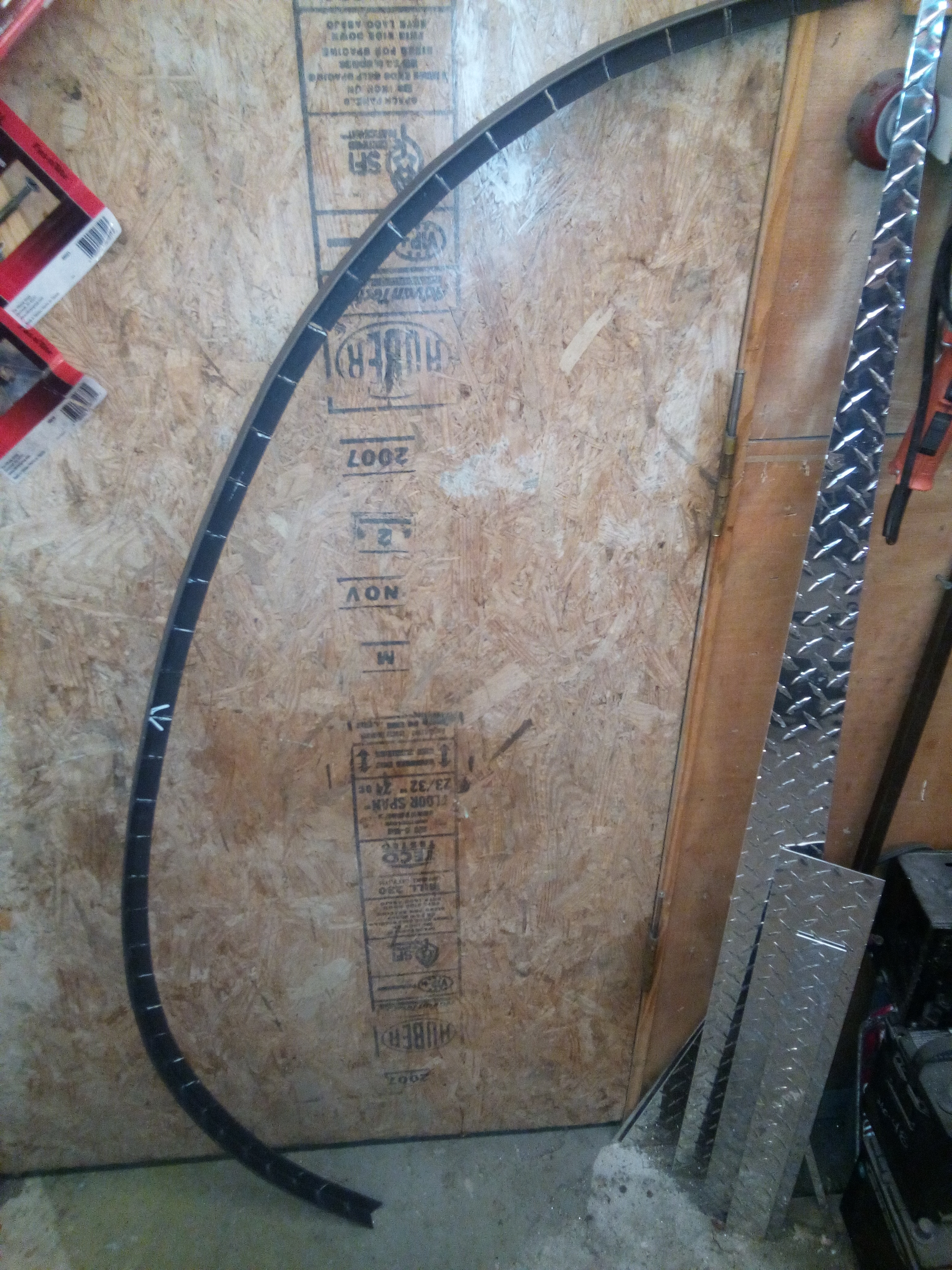
All notched and rough bent to shape.
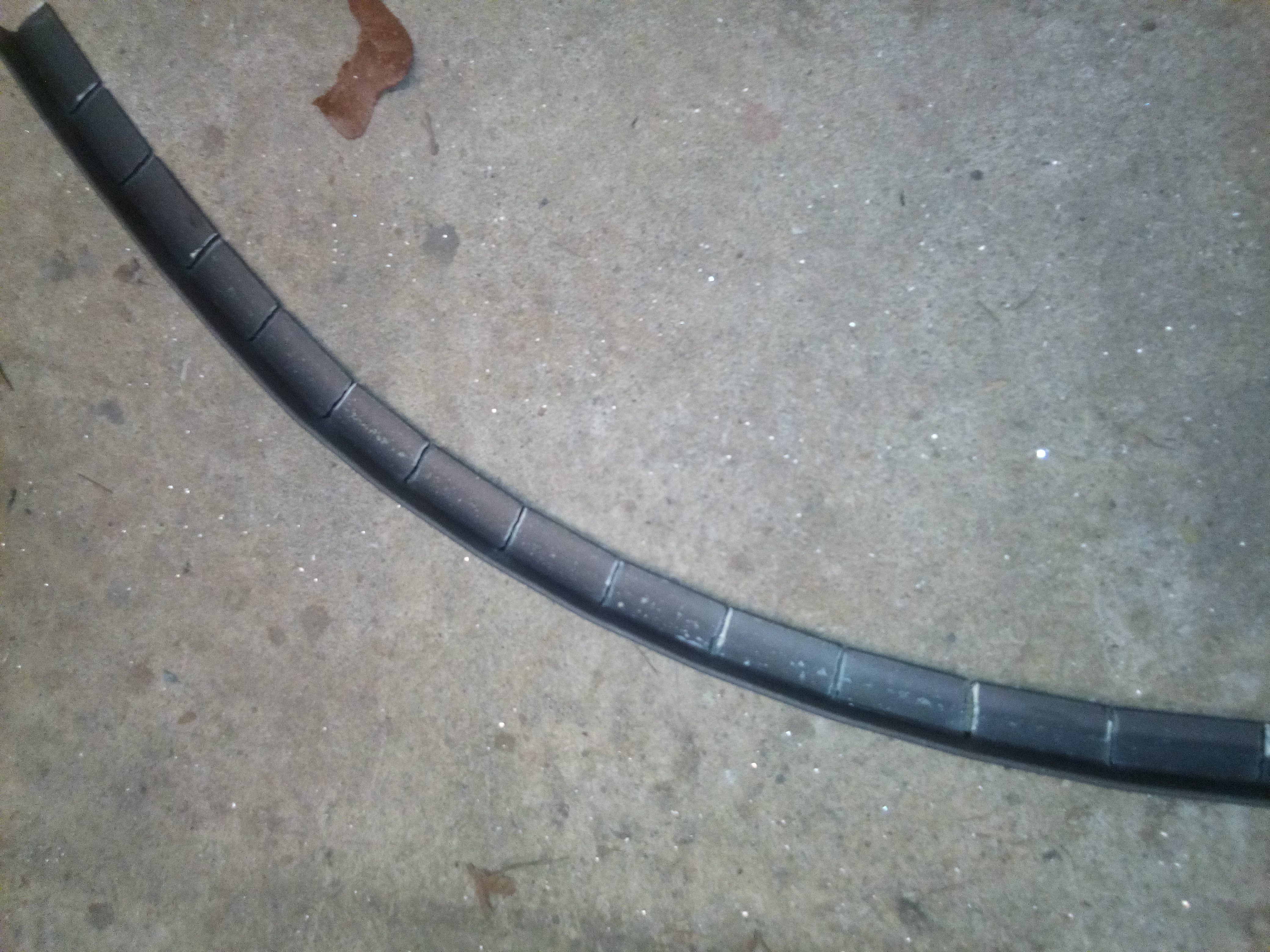
Notched every 2".
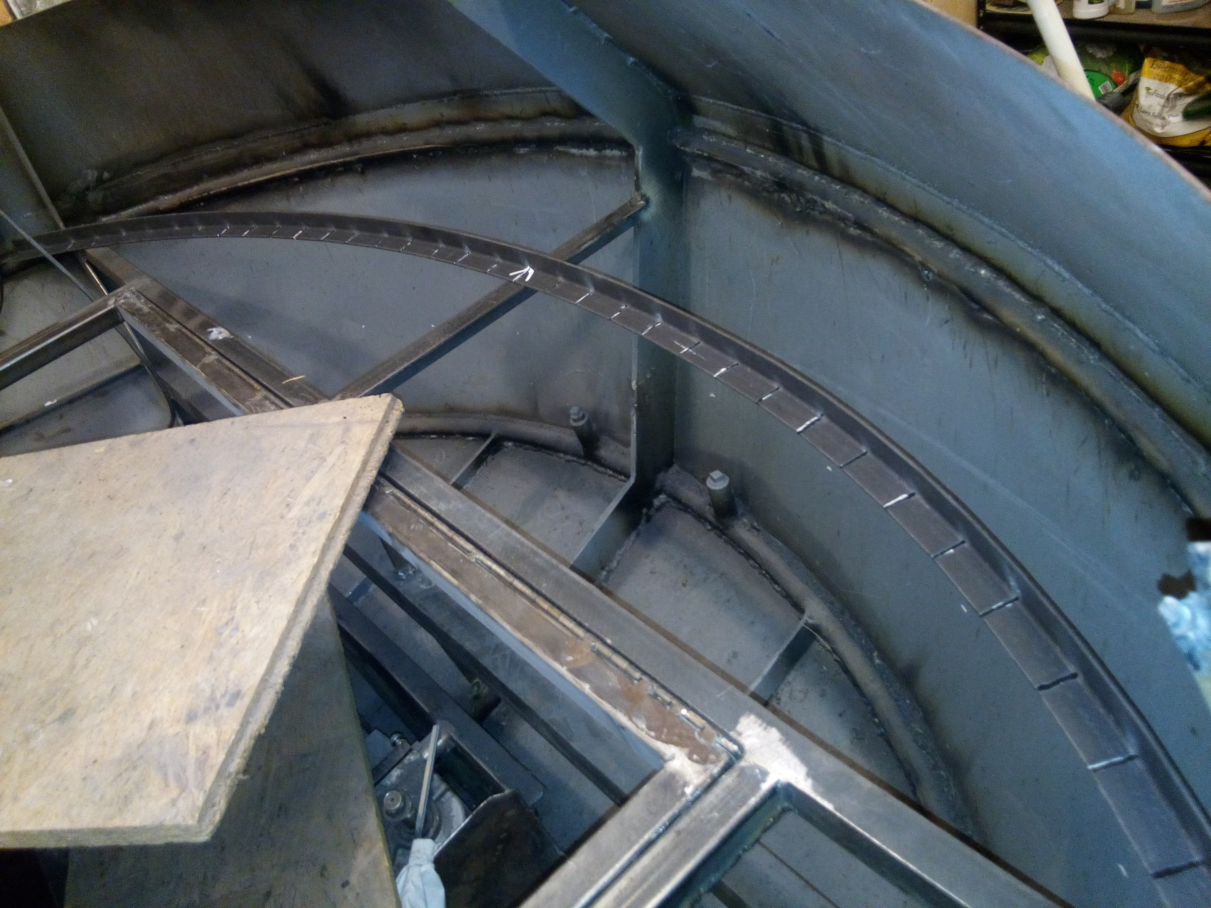
Edge angle in place and to contour before welding the notches up.
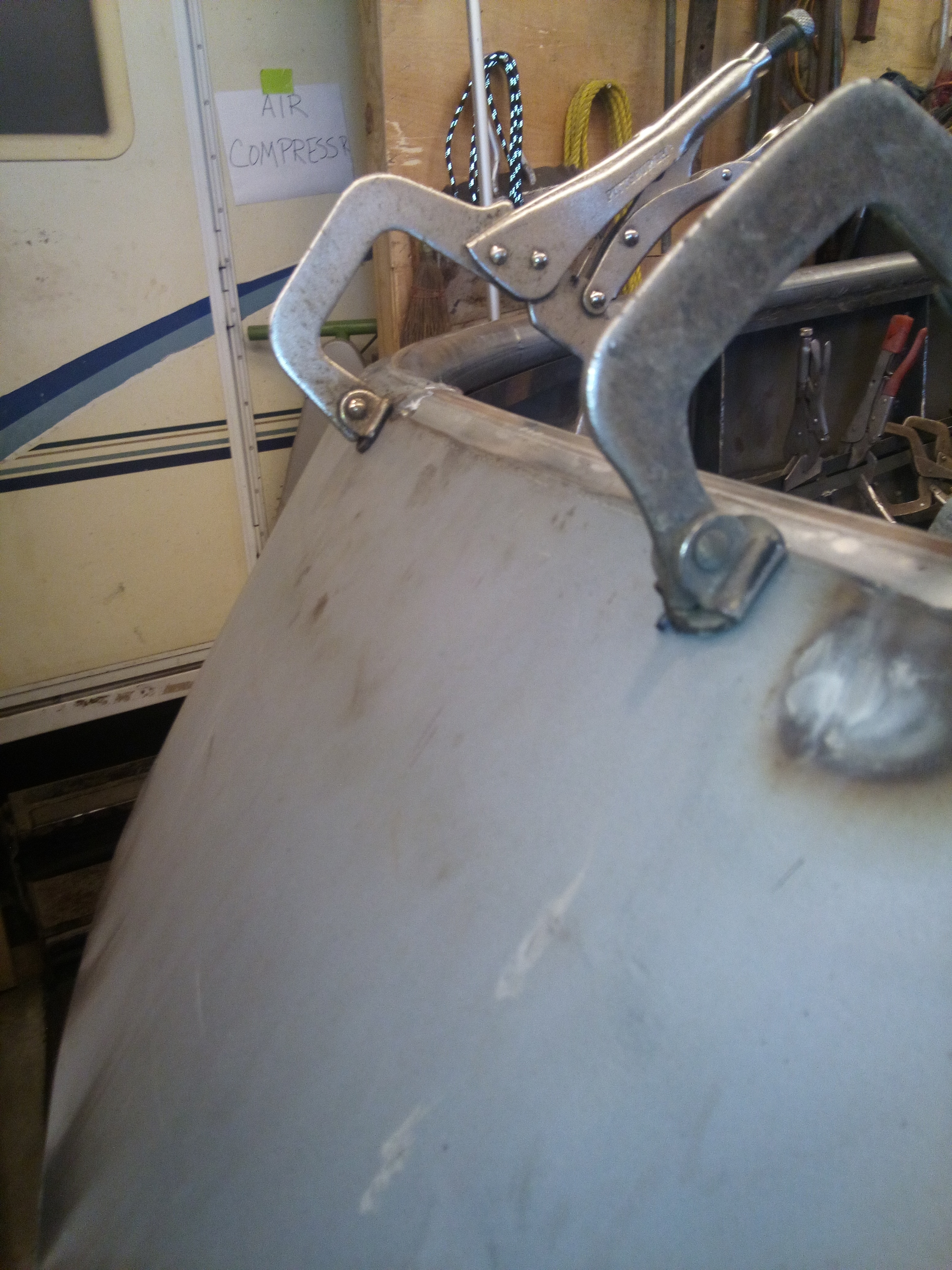
Finished forming and installing the aft P & S top rails to the bulwarks. There are several pictures here and this is the detail... In proper form, I formed both port and starboard rails to match the developed sides. However as I got near to the aft quarters, the curves got excessive for my roller to manage without deformation. So I opted to make a third member that went around the stern, and connect the two side pieces.
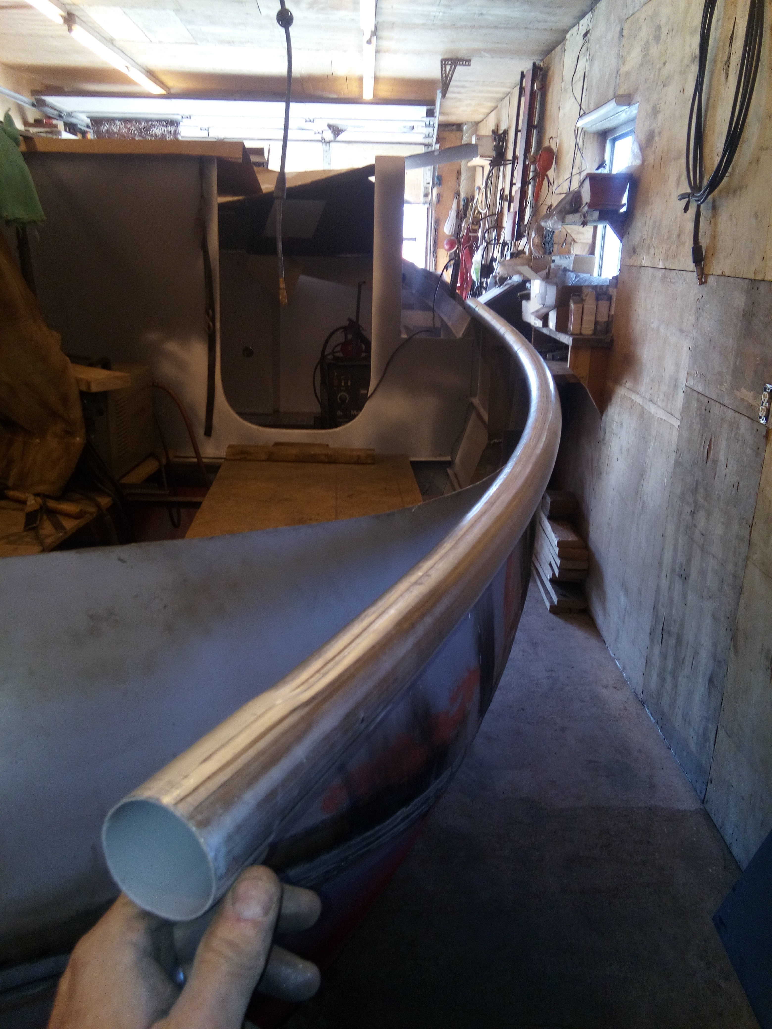
Starting the curves, shallows first.
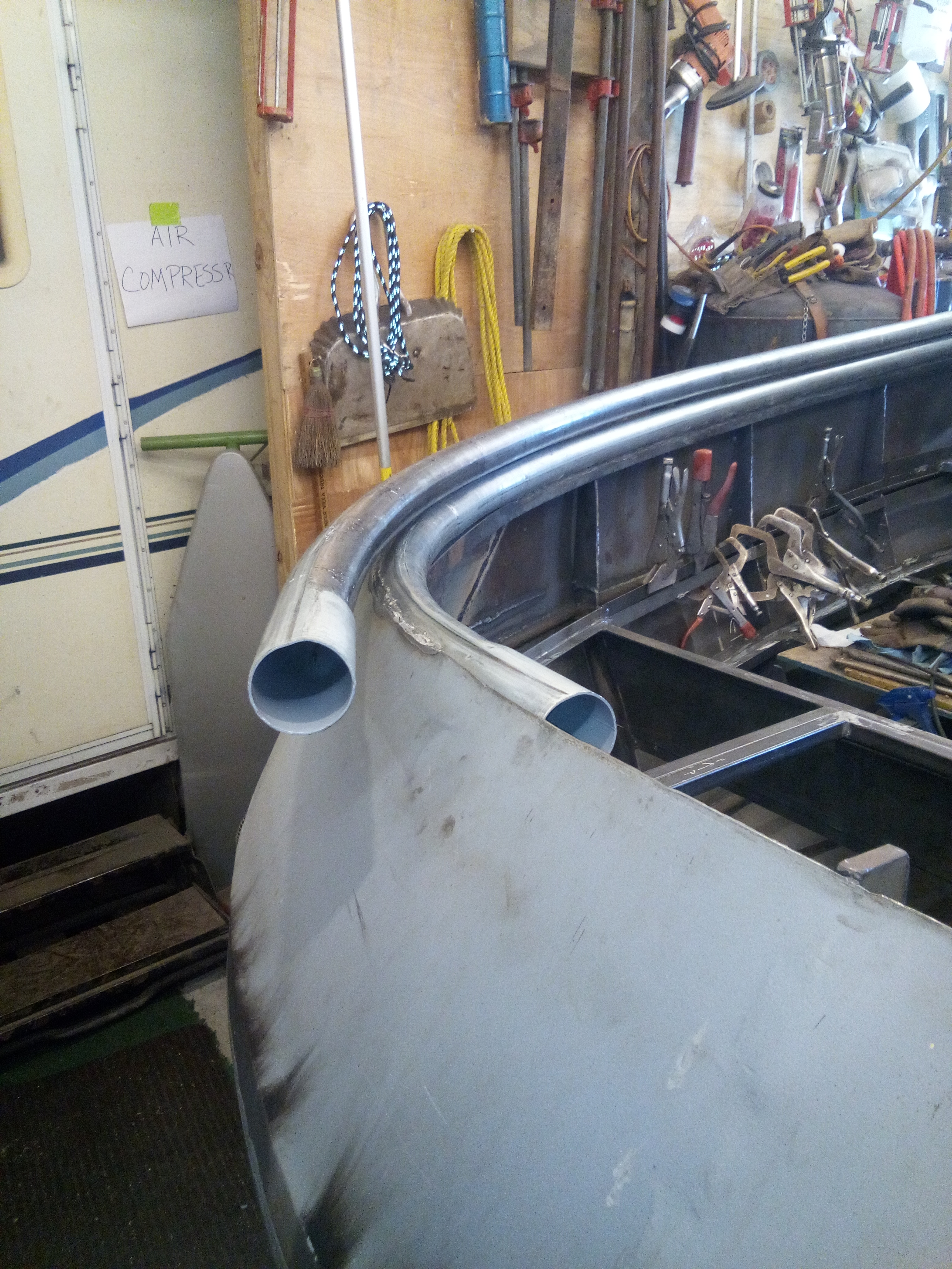
Matching the curves, left = right.
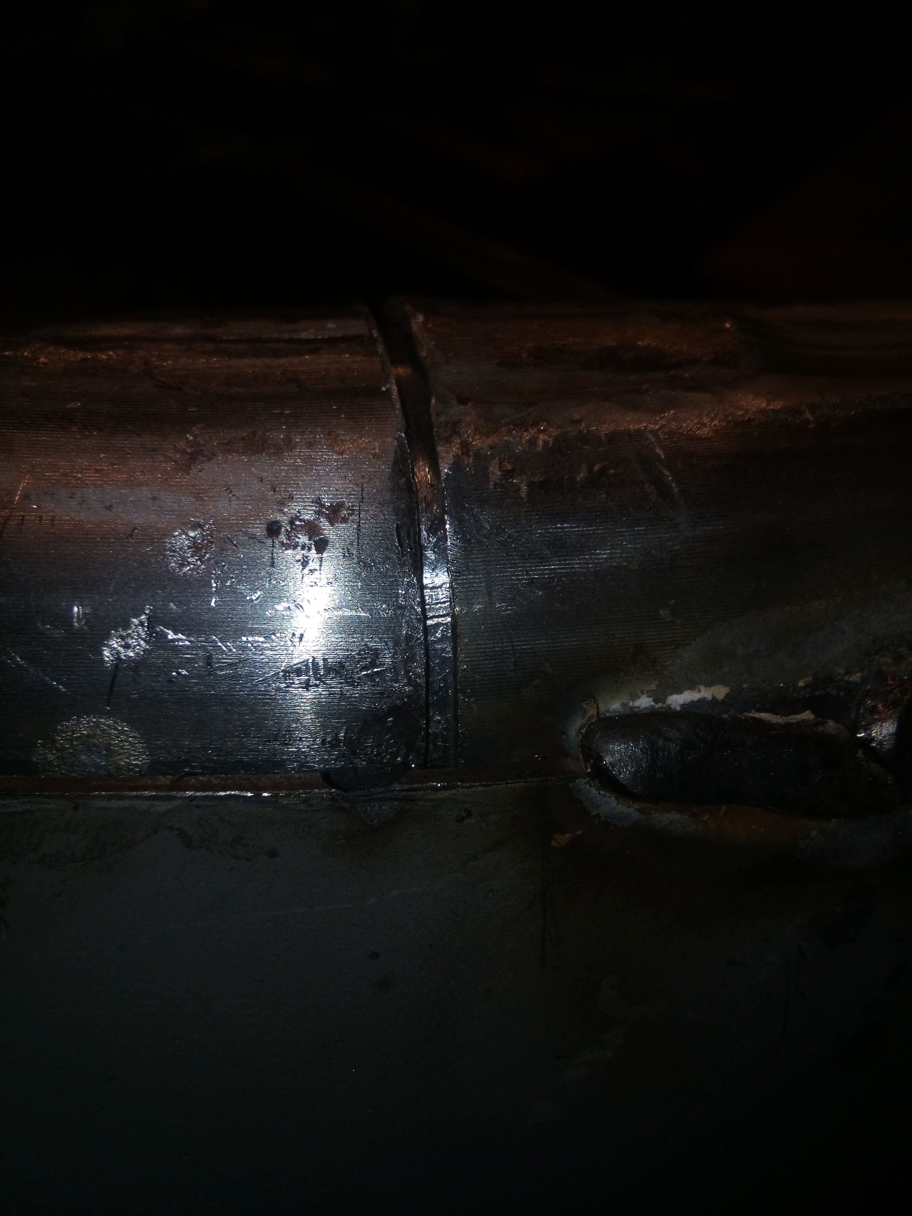
In a splicing like this, where there is a complex and compound curve, I made one side a standard perpendicular cut to the ends of the matching components. But on the other end, I "45ed" the mating ends, and left the splice 1/2" longer than I thought it needed.
3rd member cut slightly long.
Notched the stern post to receive the top rail.
fitting the 3rd, fantail member.
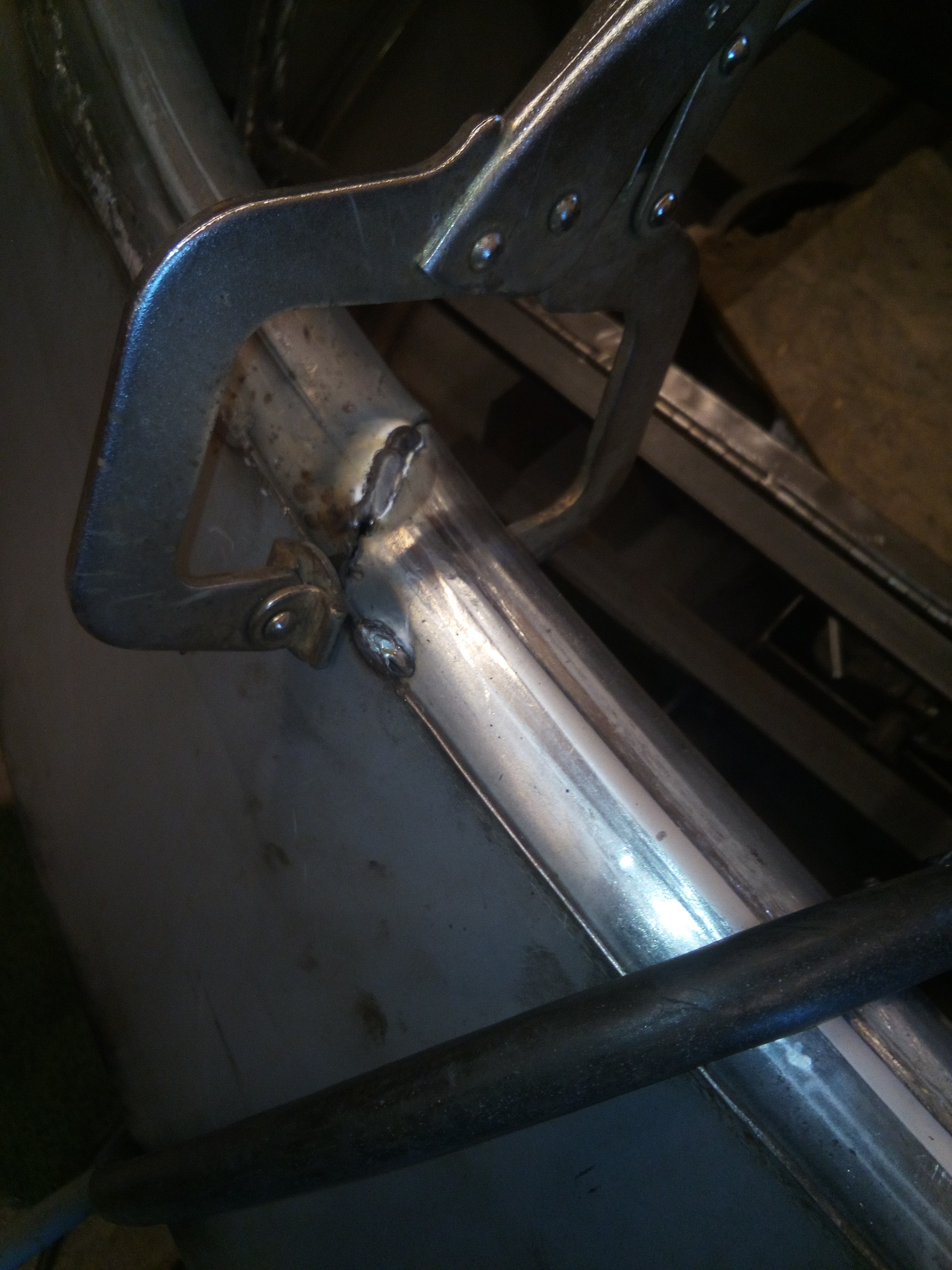
90ed sleeve.
45ed sleeve before halfing.
Then I made a sleeve from a scrap of the conduit, to make a mating guide for the squared end. This will also add reinforcement to the strength after welded and reduce distortion. On the 45° end, I took a piece of the drop I cut off that end (which had the desired cut angle), and split it to give me only the inner half. This was tacked into the inner mating point to give the same mating reinforcement as the other side. It sounds more complex than it is...
"floater" sleeve in place.
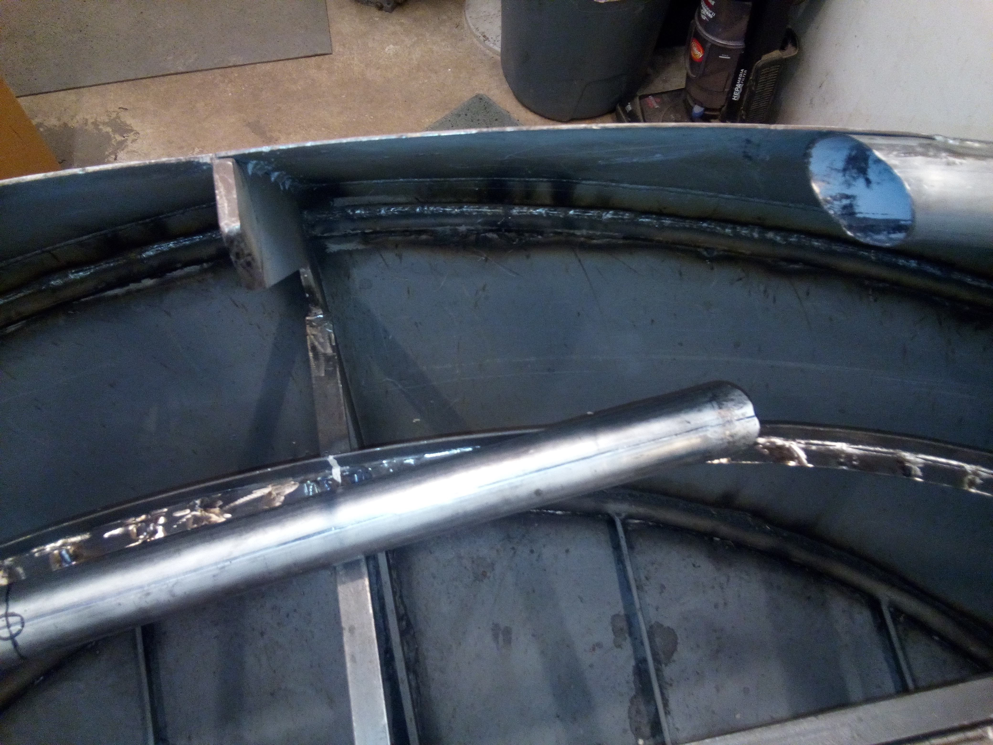
Then as I began the finish fitting, I started grinding to fit the 45° end, and kept a reasonable amount of pressure on the third member to keep it touching the side member. In this case, it was the starboard side member.
Once I was satisfied with the fit, I aligned the rotational positioning, and tacked it in place. And, moving from the 45ed end, to the 90ed end, I tacked it every 2" or so with a small 1/4" tack-weld. After that, it was just a matter of short 1" stitch welds and periodic squirts from my spray bottle to keep the parts cool enough to prevent pulling or skin distortion.
45ed end alignment.
Ready to tack down the skin.
You will note that the 90ed end, also noted as the "floater" end was tight at the beginning of the operation, but once the last piece was fully welded in place, there was the obligatory 1/8" of gap for filler welding to finish the joint.
"Floater joint" ready to weld after the outer skin is fully welded to the top rail.
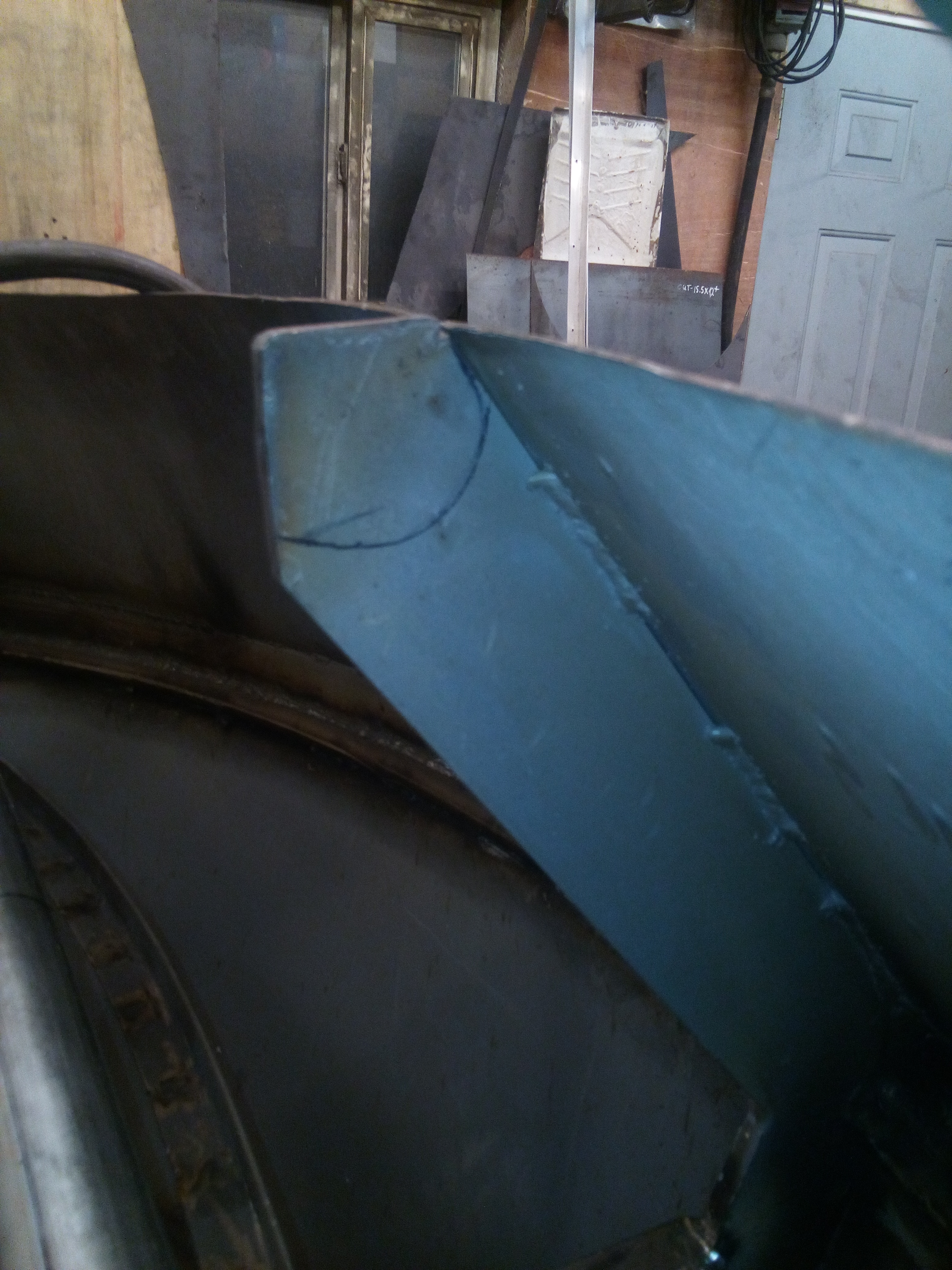
Then I cut and welded in the inner structure so I would have a more finished look to the outer parts of the tug. This will also make it easier to seal up the boat from inclement weather.
Inner panel structure getting welded in place.
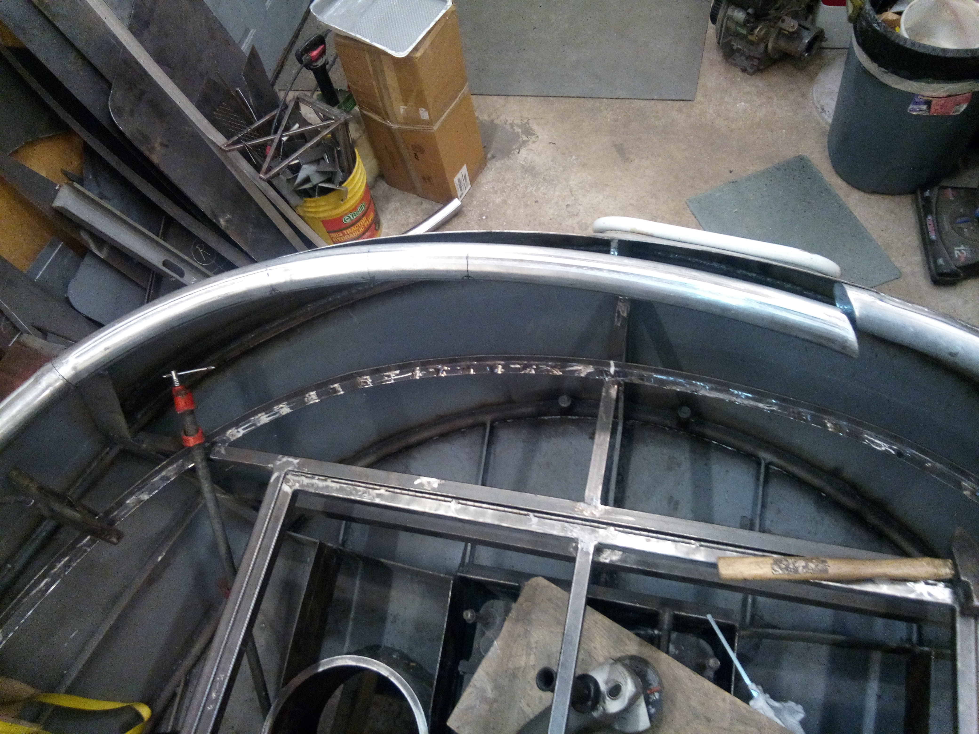
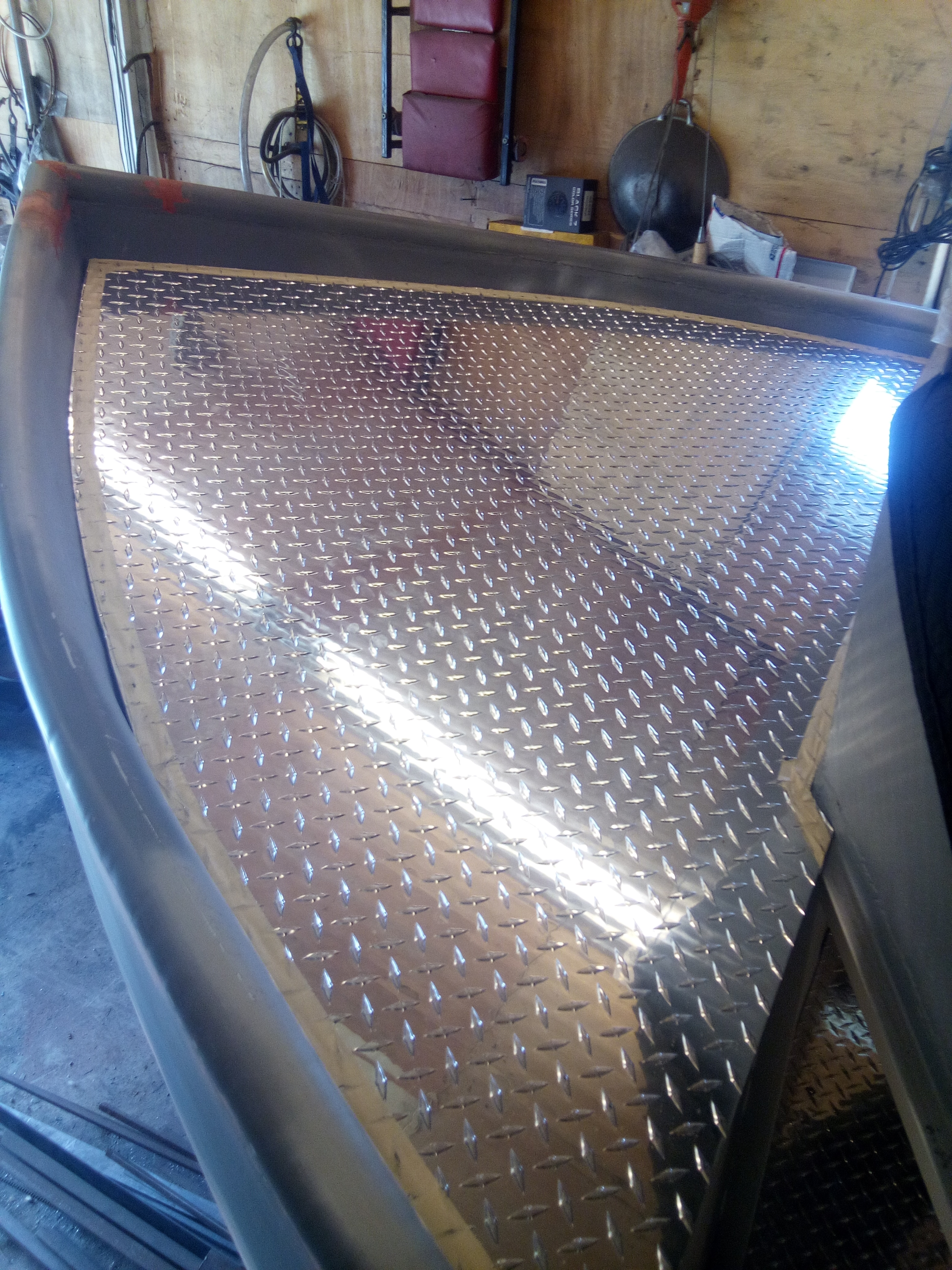
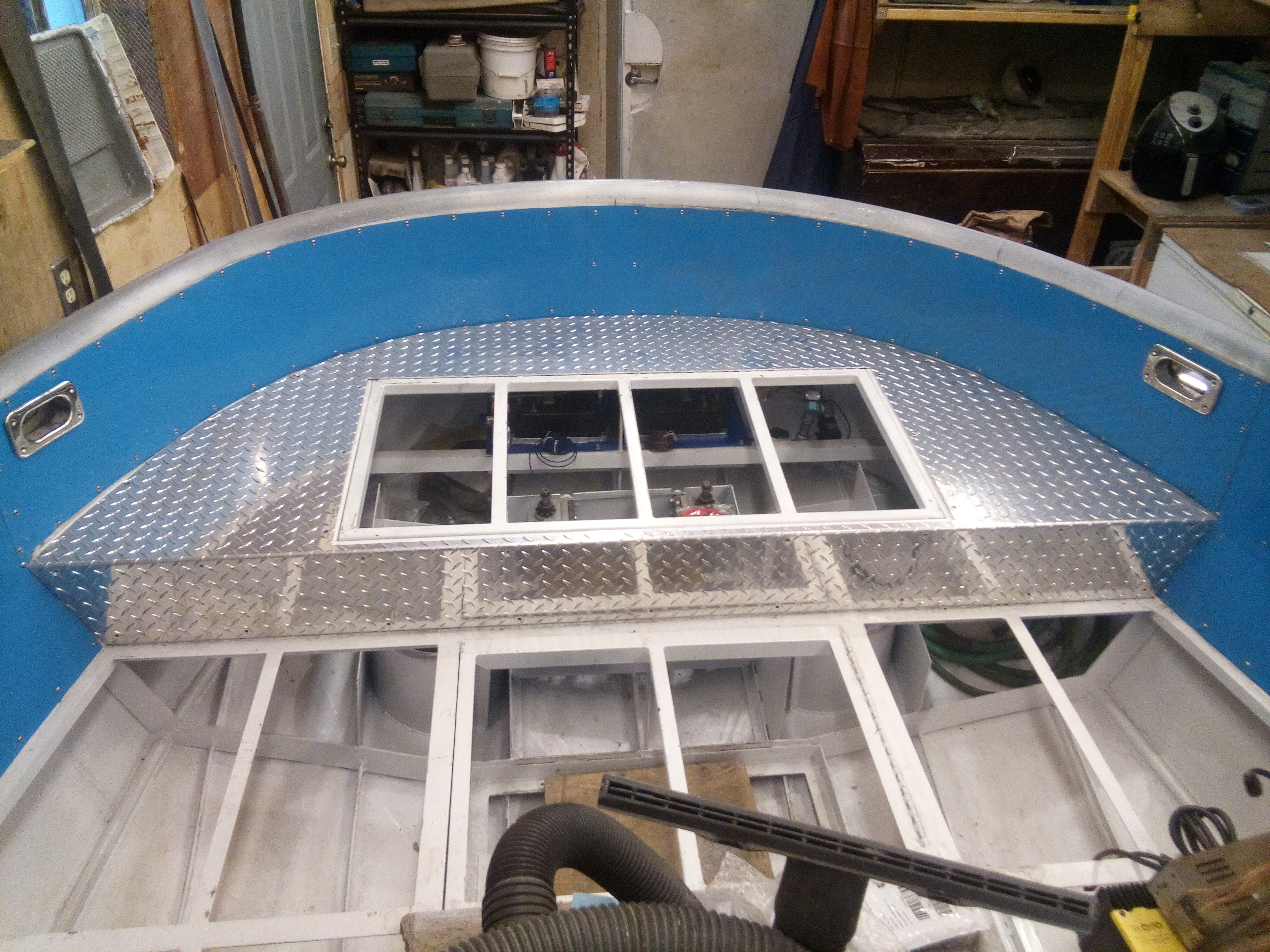
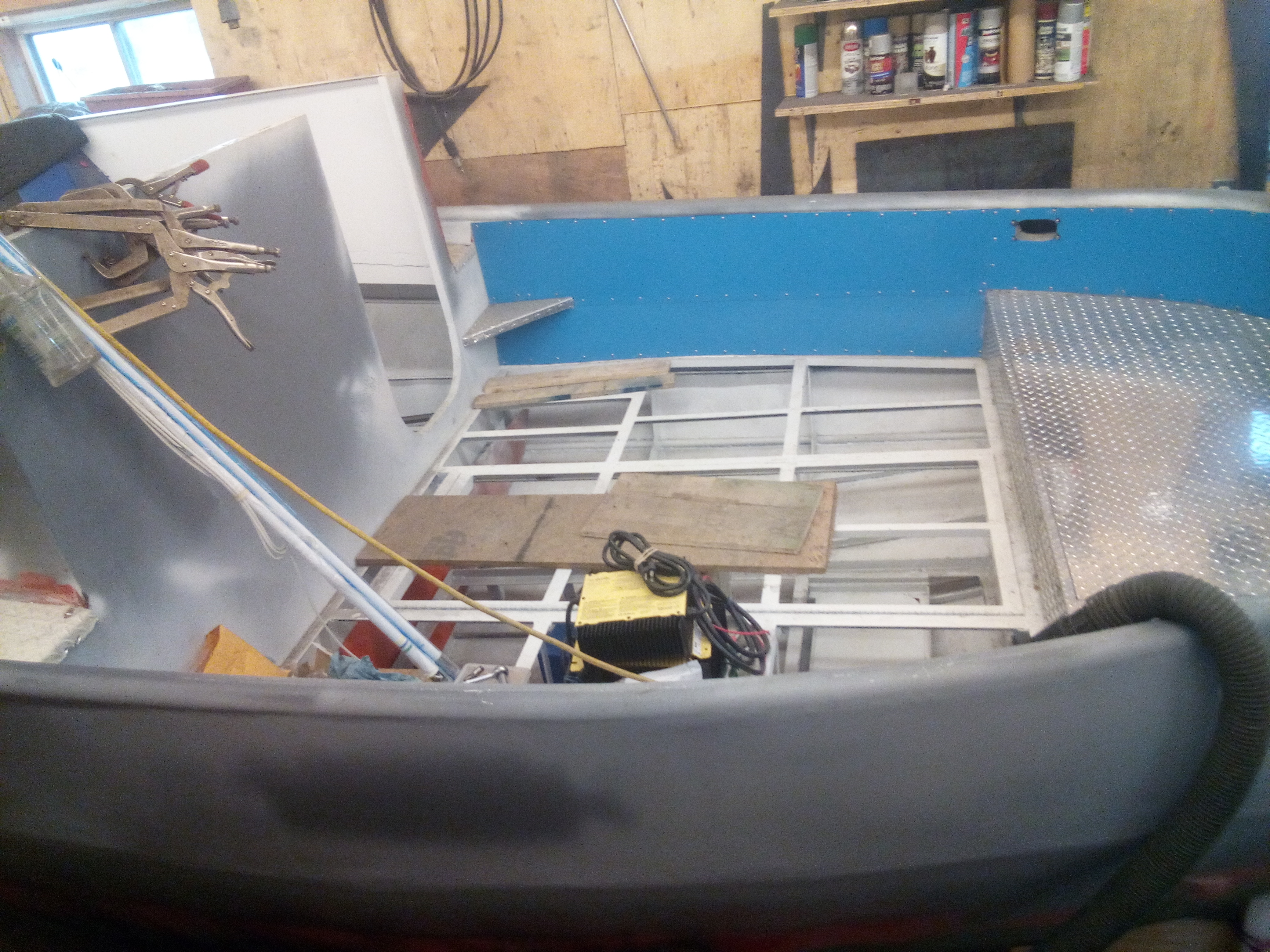
Finished up fitting and installing the aft motor bay hatch lid, and installing the deck supports so the .125" Aluminum tread plate won't be so springy under my feet.
1/8" & 14 Ga. support members all in place.
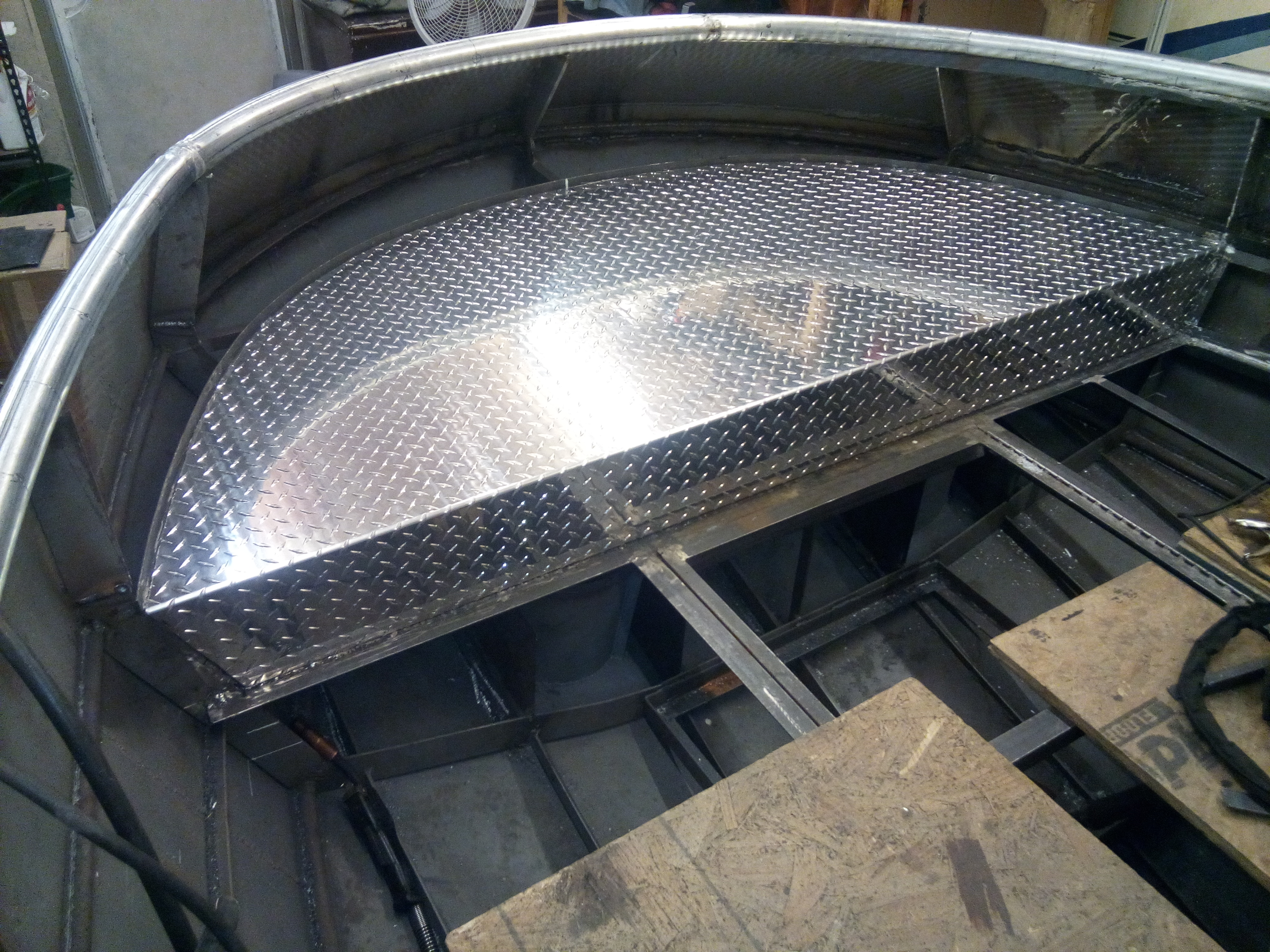
Rough cut and fitted the raised fantail deck plate prior to painting.
Then it was on to cleaning out the back half of the bilges for primer and paint. That took a day with the scrap metal barrel handy, and the shop vac with a new filter... I did not realize how much gonja had built up in the bilges while I was focused on the other welding and construction.
I used a combination of a coarse rotary brush in a drill, and an even coarser shell brush on one of my 4" grinders (without a guard so be watchful). More finish grinding, more vacuuming, etc, until it was what the military calls, "clean, dry, and serviceable."
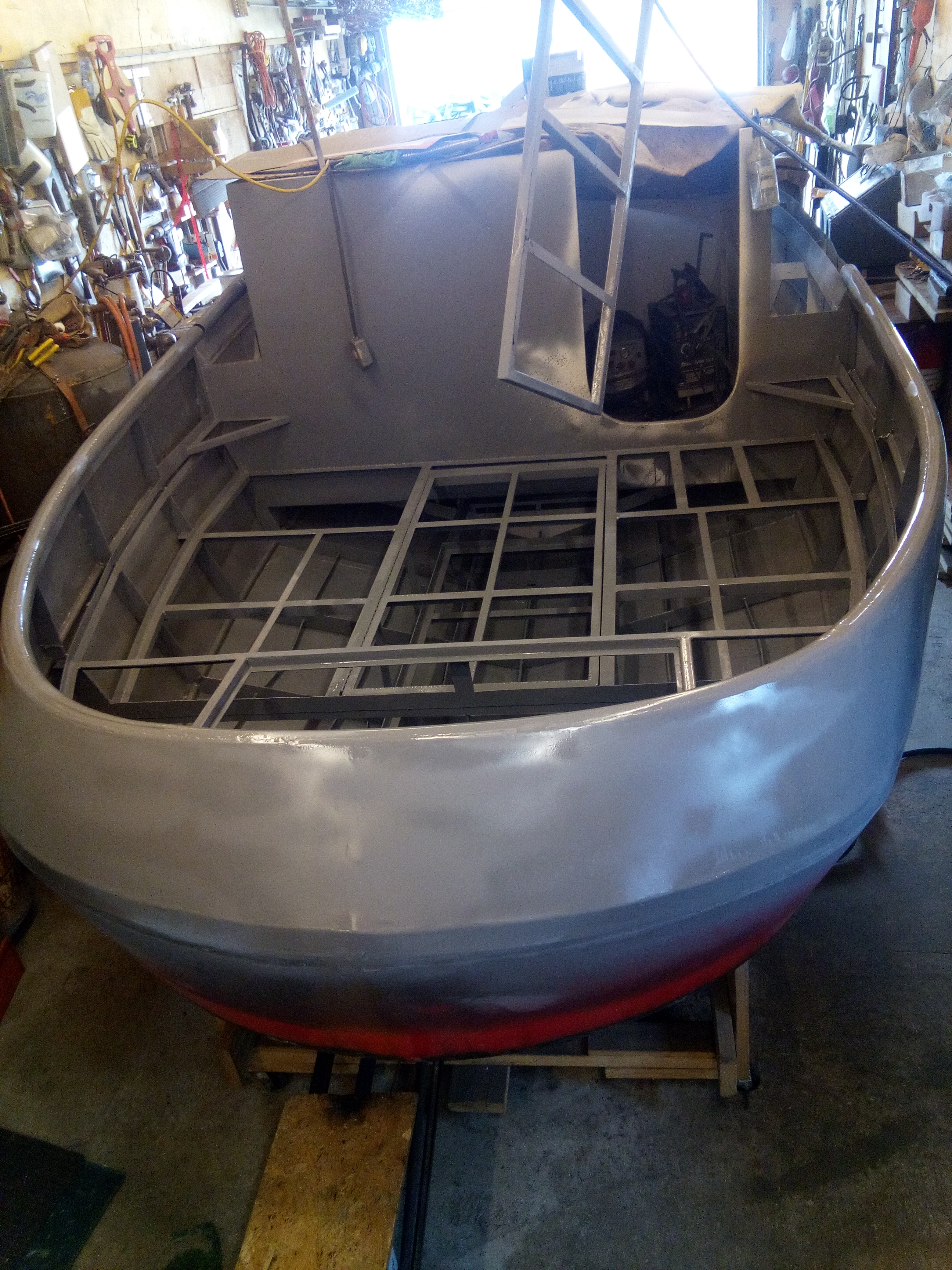
Monday Morning the 5th, I started the priming with a super grade of marine type "Mare Island Grey" epoxy primer. This stuff is 50% solids. That is a lot more than your typical automotive grades. A word to the wise here, ... bundle up before spraying this stuff! It will get in every place not sealed from it!
Here I will take a moment to discuss an experiment I did that worked out very well. In priming and painting the forward bilges, I had significant difficulty spraying under the deck framing, and in those "hard-to-reach" places. So I was actively looking for a simpler and easier way to insure every surface was coated.
I went to my Local Lowes, and bought a cheap garden pump sprayer. It was only $9.95, and would hold about a gallon.
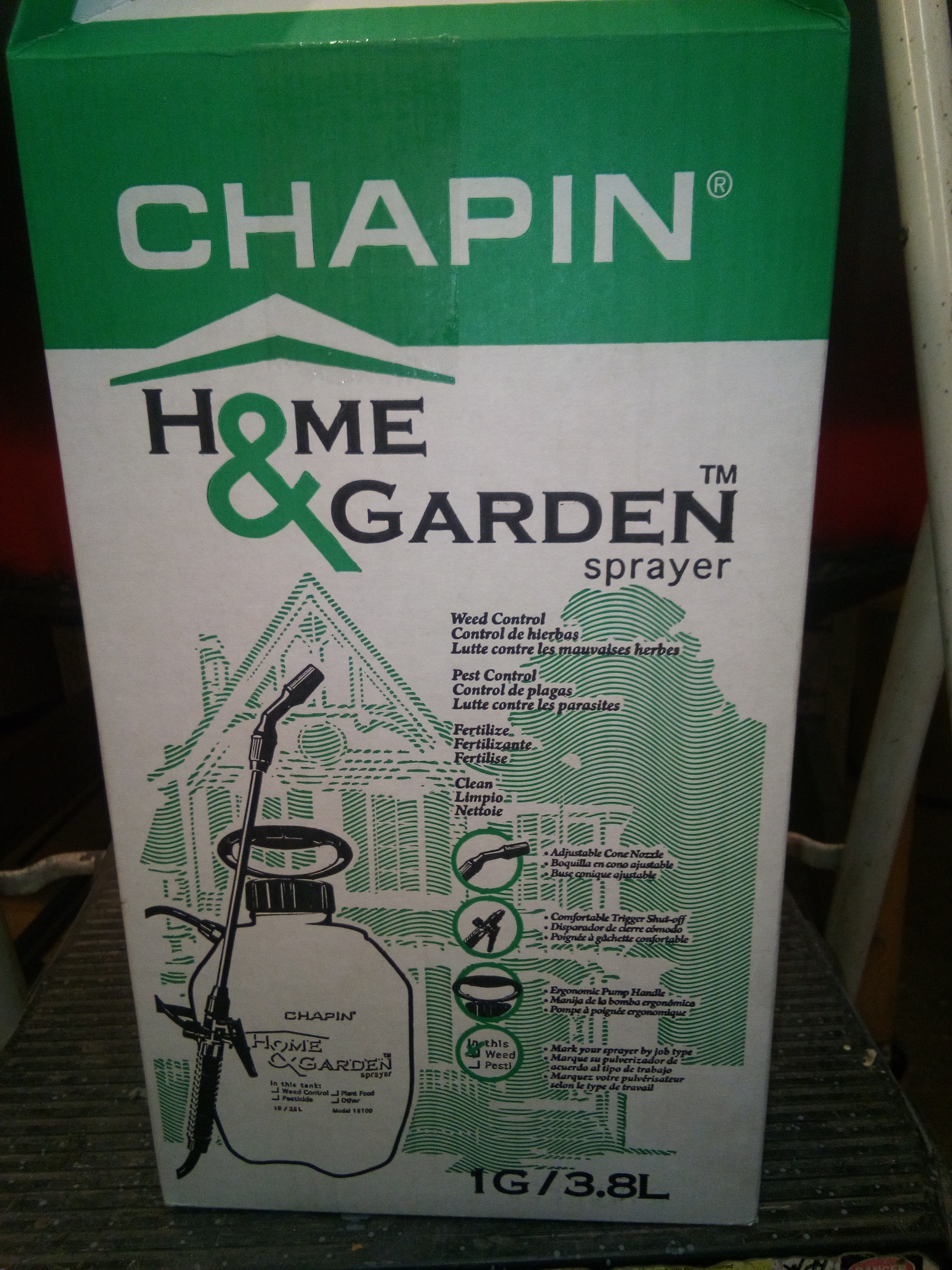
Cheap garden sprayer.
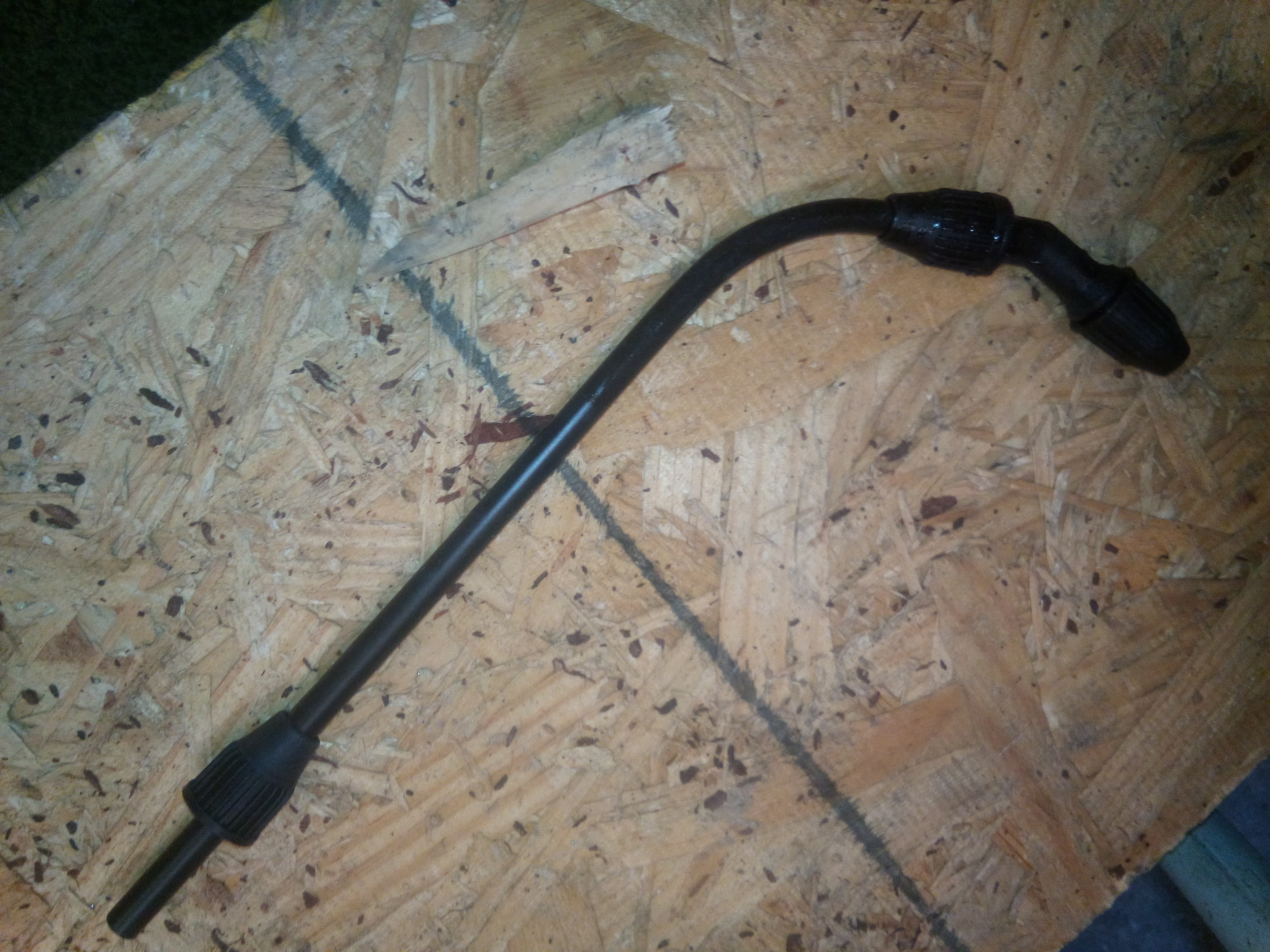
Slight wand modification.
Once assembled, I removed the wand, and with the delicate finessing of my propane torch, I got a section near the nozzle up to the desired 170°-185°. At this point, most of these thermal plastics become maluable. I carefully added some bend to make the nozzle now point about 100-135° from the handle. That is something over 90°, it is not critical.
It worked!
The primer I chose for this job, is a very heavy epoxy that had an activator that was right at a quart for the gallon. I know everybody has their favorite, but I chose this for its chemical properties and success in the commercial world.
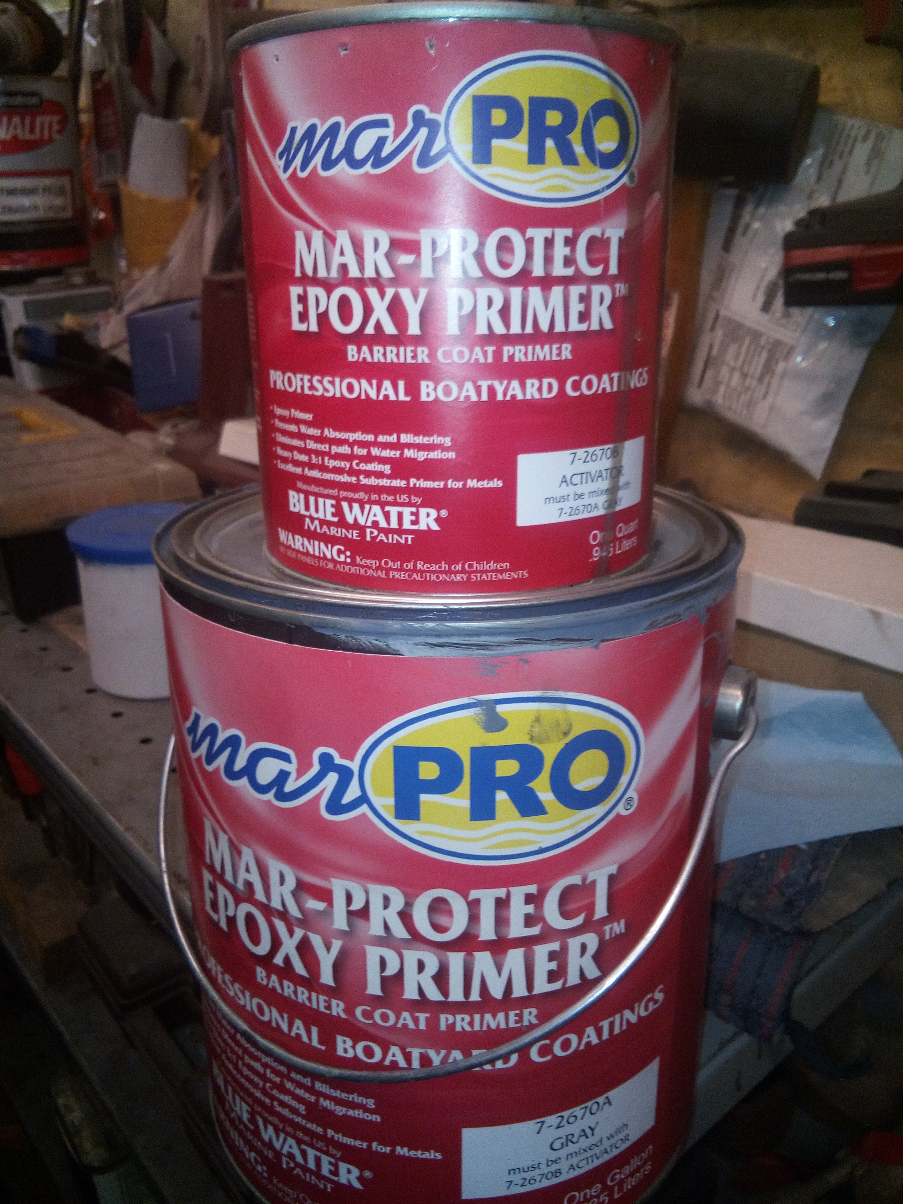
My primer of choice on metal boats.
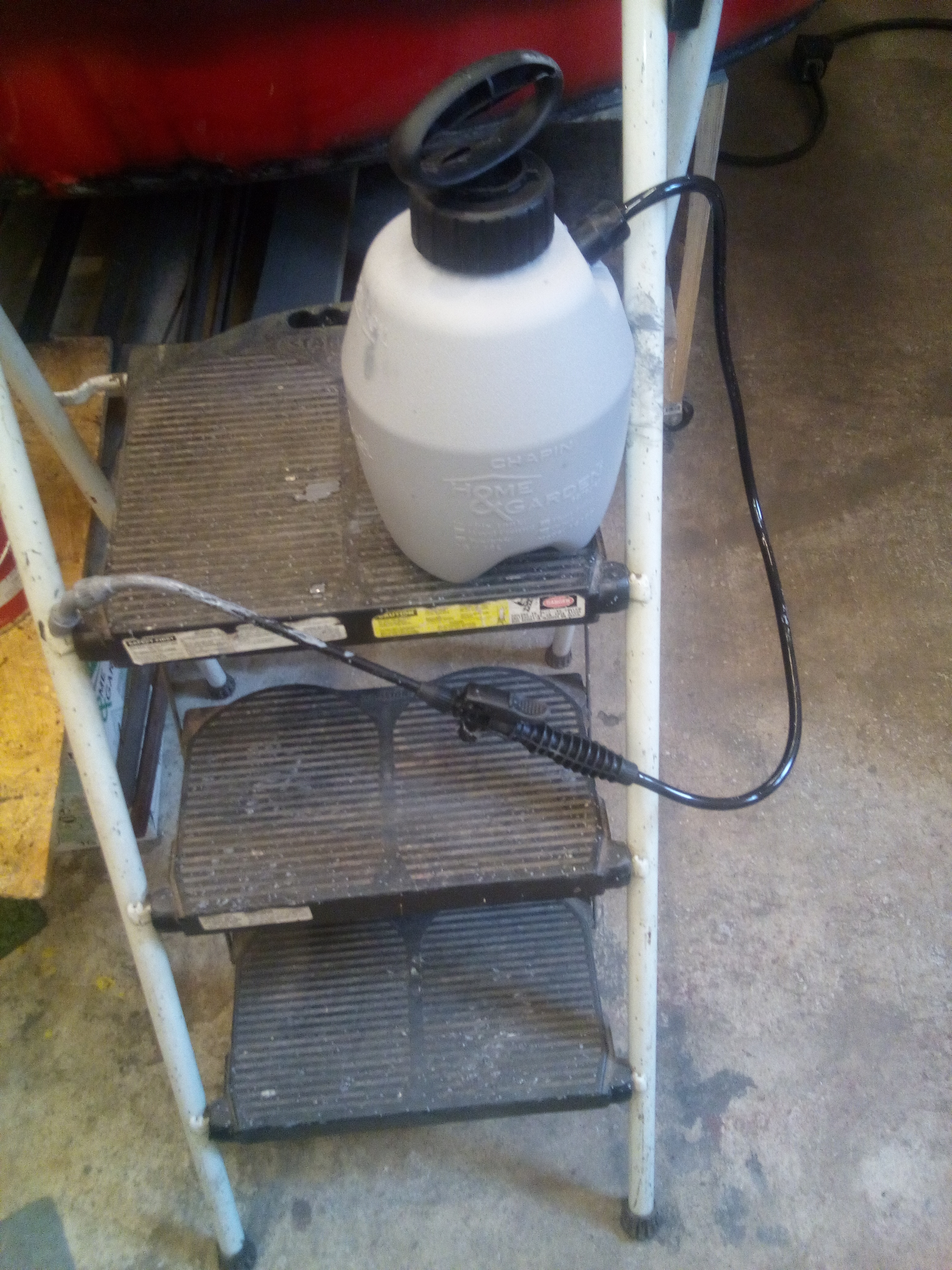
Filled with the reduced primer, and pumped a couple shots of pressure. IT WORKED SUPER!!! I was able to squirt primer EVERYWHERE I could not see! I needed to keep pumping it up so the spray pattern would be enough, but I ended up squirting a full half-gallon on all the undersides without so much as a drop on me or the walls of the shop.
Another half-gallon in the spray gun, and I was done before noon.
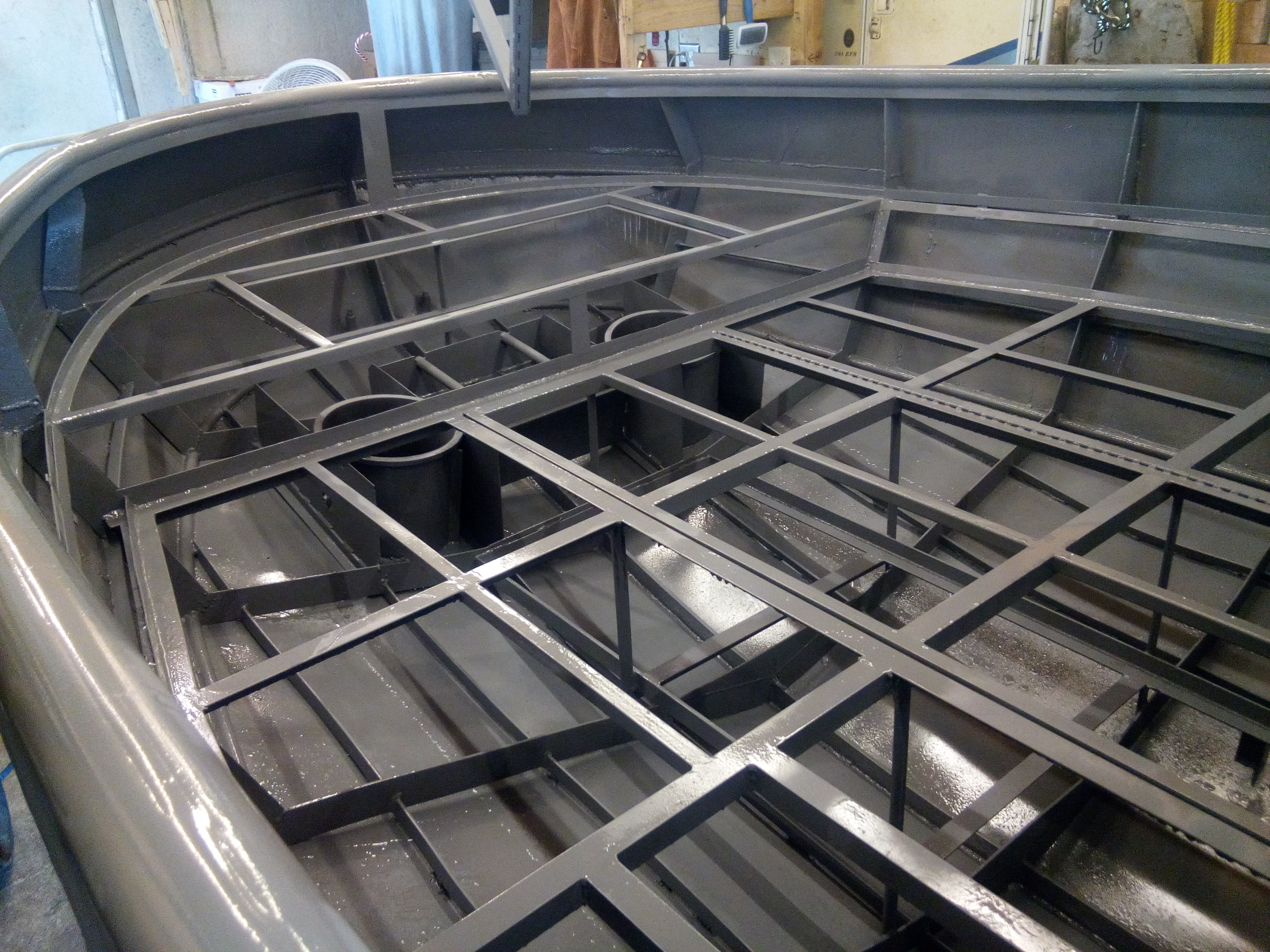
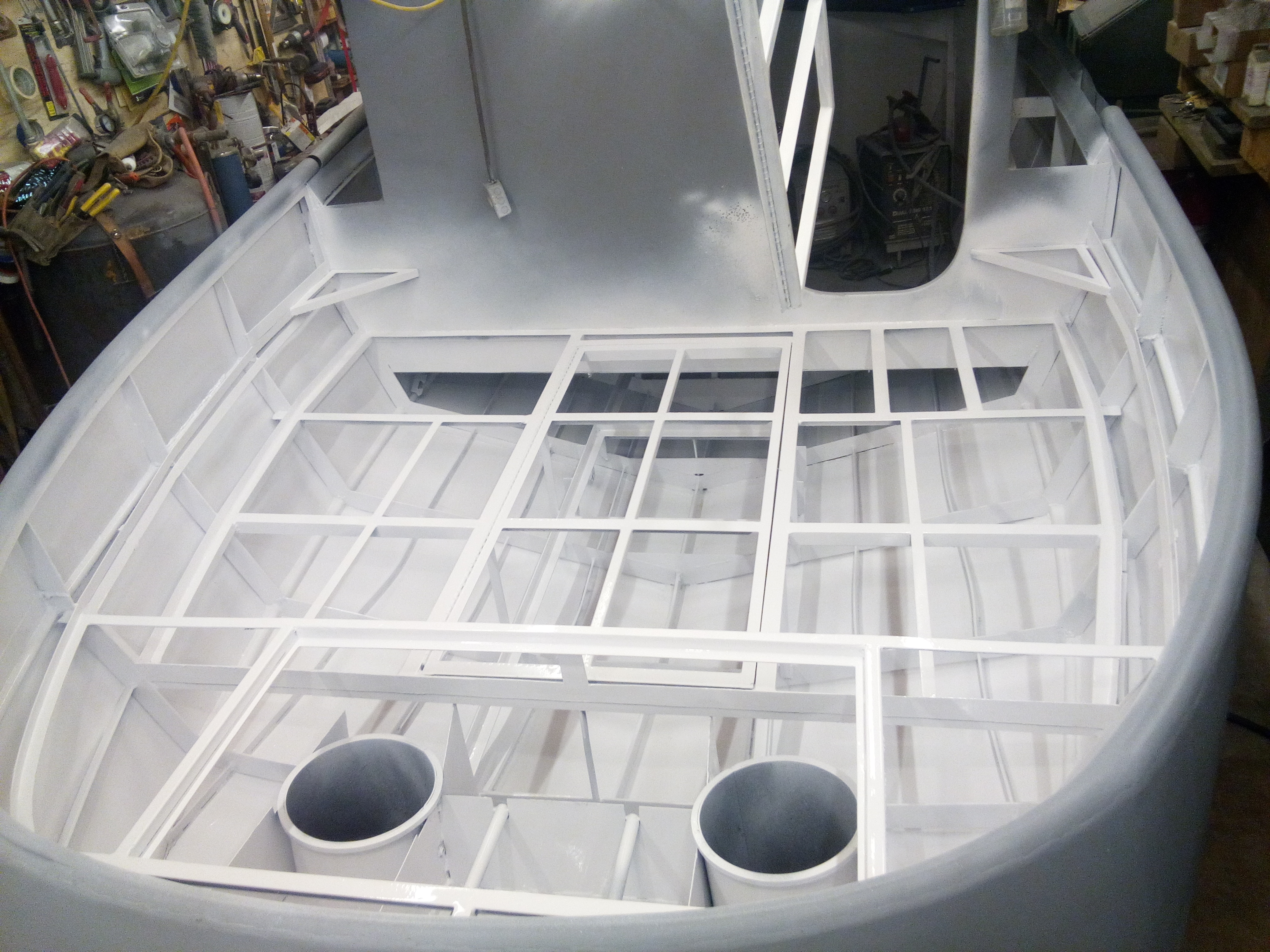
Entire back half primed before noon.
By early afternoon, I had waited enough time to have the grey set up, and it was time for the white bilge colour. I did the last spraying of that gallon by 6:30 PM. It was a full day of painting, but the results were wonderful. No bald spots, no missed areas.
Note: A word about Marine painting I have learned... I see a lot of people that struggle with getting a decent finish on their project. I can tell you, that back when I was in Autobody college, they hammered into us, the finish, from start to finish could be no thicker than 12 mils thick (and preferably 6-8). We had to prime, seal coat, base coat, and finish coat all within this thickness. We were hammered to make it slick, but make no dry spots or runs. Top coats had to be 3 mils thick or less. That is fine generally and for auto painting.
I have found with my experience as a painter/blaster for the US Navy up at Sub-Base Bangor, We had to make a similar surface finish, but the "boat", had to withstand months of harsh climate in the coldest seas, and the roughest of conditions. We found, that the best protected parts of the hulls we did, were those that we, 1, properly cleaned & etched, 2, heavily primed, and 3, sufficiently painted. This might sound a bit "primaryish", but the builder needs to concentrate on the fact that there is no substitute for enough material to accomplish the job. Don't skimp on the paint film after spending so much time to build it yourself in the first place.
We were taught, that the "thinner", or "reducer" was NOT a part of the finished paint, like in a car. In a car, after the painting was done, only some of the reducers were gone, but there was still artificial thickness from embedded, slow escaping solvents. And, in a car, there are hard impacts with other car doors and other things that required that the finish be extra hard and thin. The environment of a boat is far different. There needs to be enough paint on the surface to withstand the constant abrasion of the water and water-born particles, (trash, logs, weeds, marine life, etc), and still provide the slick impervious finish to protect the structure it is coating.
I used this knowledge to make sure this project would be well protected. I shot multiple coats of primer or paint, to protect the steel under it. So my suggestion is to not skimp on the coatings. If you get a hanger or run, that is OK. It can be sanded out later, or in the case of a run or drip, can be taken out immediately after spraying, with the sticky side of some masking tape. All the marine paints I have used over the years have a slow enough cure or dry time as to level out after "taping" a run. The end result will be a bright and slick finish to be proud to say you painted.
So now, "Oie matey, them bilges be white"! "Now fer sum decks ta swab"!
Almost need sunglasses to look at that.
WOW! I think I can start installing stuff in a couple days!
^^^^^^^^^^^^^^^^^^^^^^^^^^^^
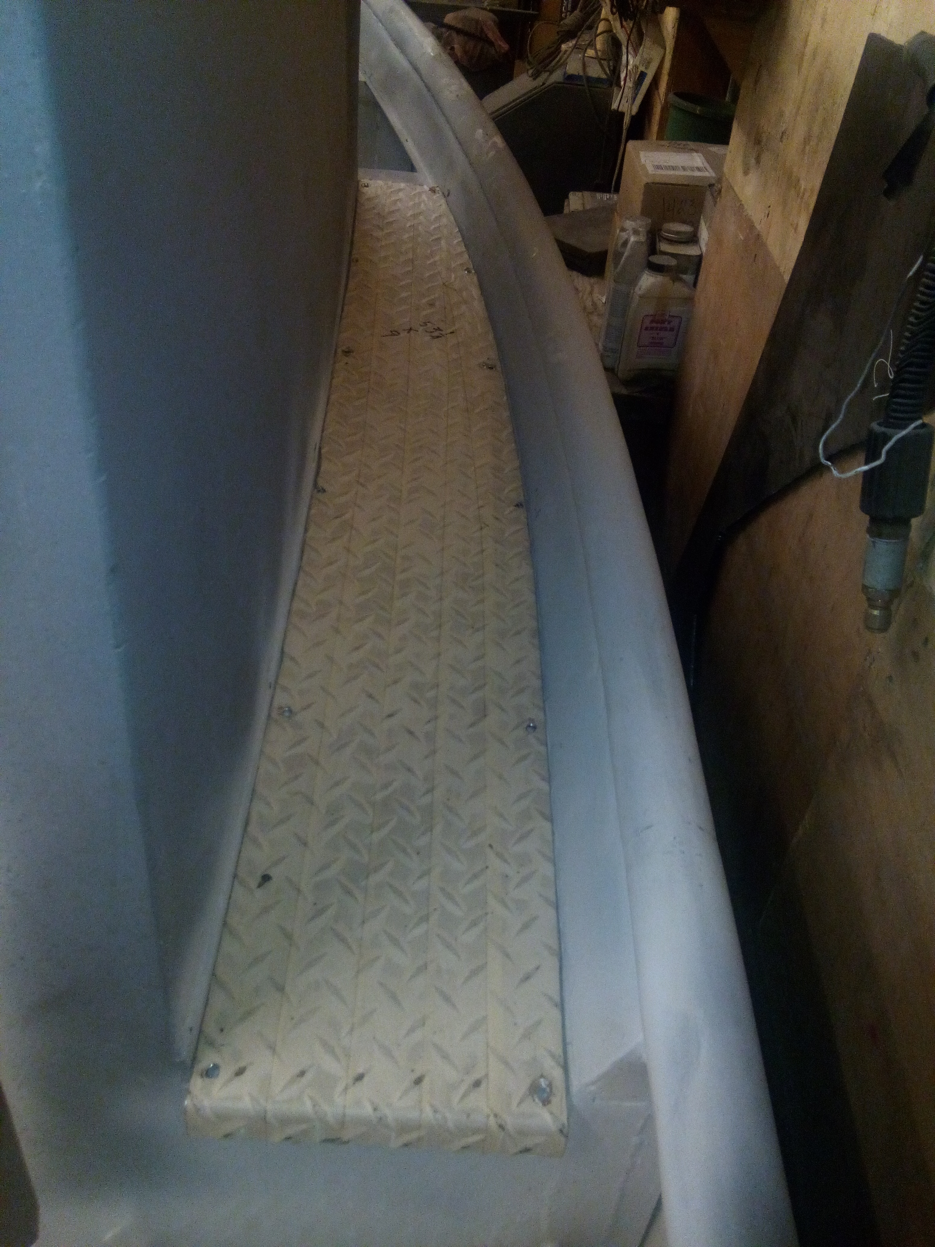
02 March, 2018 - OK, so a few days after my posting of last month, I started cutting and forming the 1/8th inch aluminum tread plate for the deck sheeting. This is a deviation from the 5/8th plywood flooring because I expect this vessel to spend most of its life out in the weather. And although you can easily weather-treat plywood, or spend the extra for factory treated, I was not comfortable having such a flammable and weather-able deck on a steel boat.
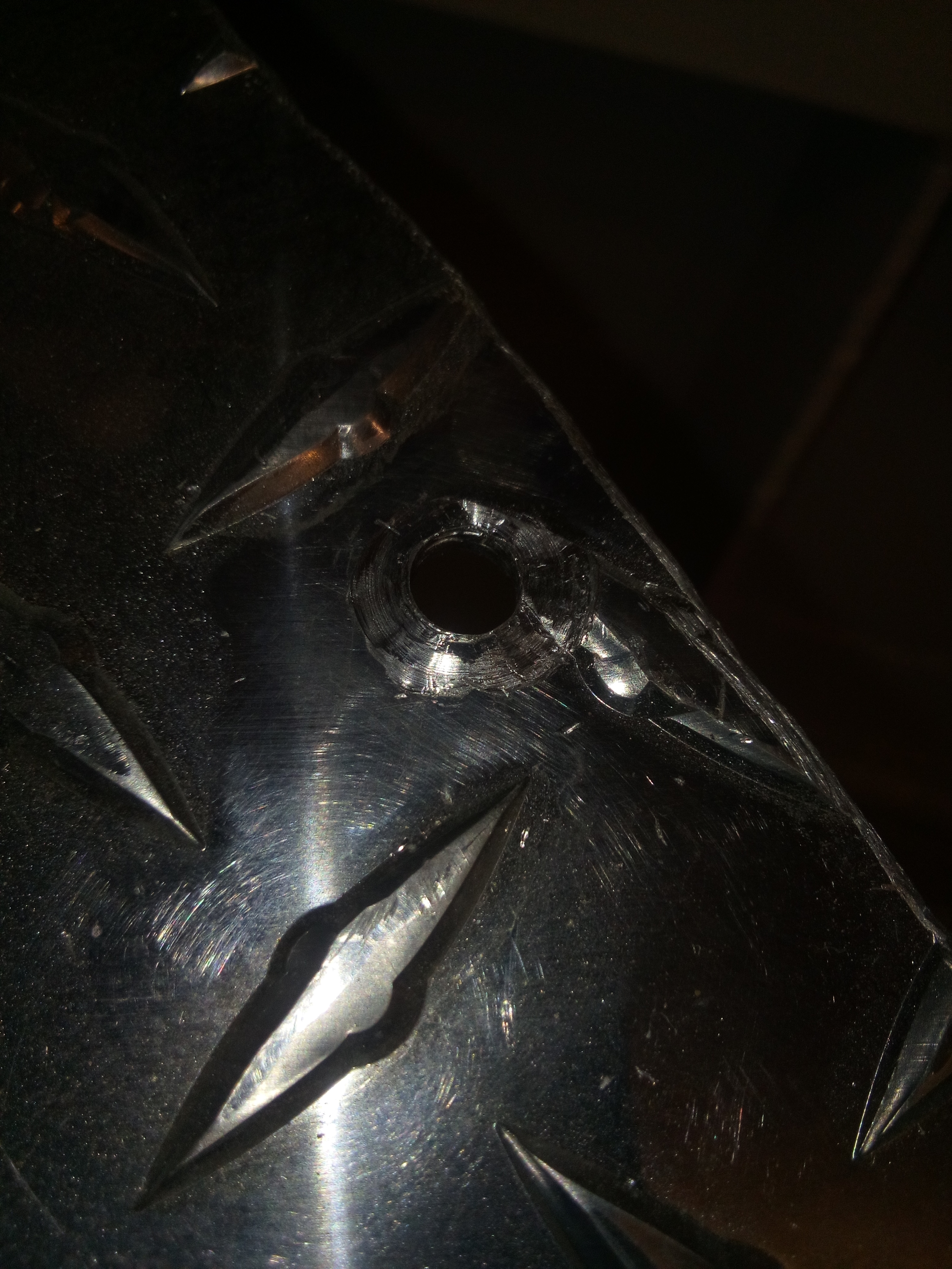
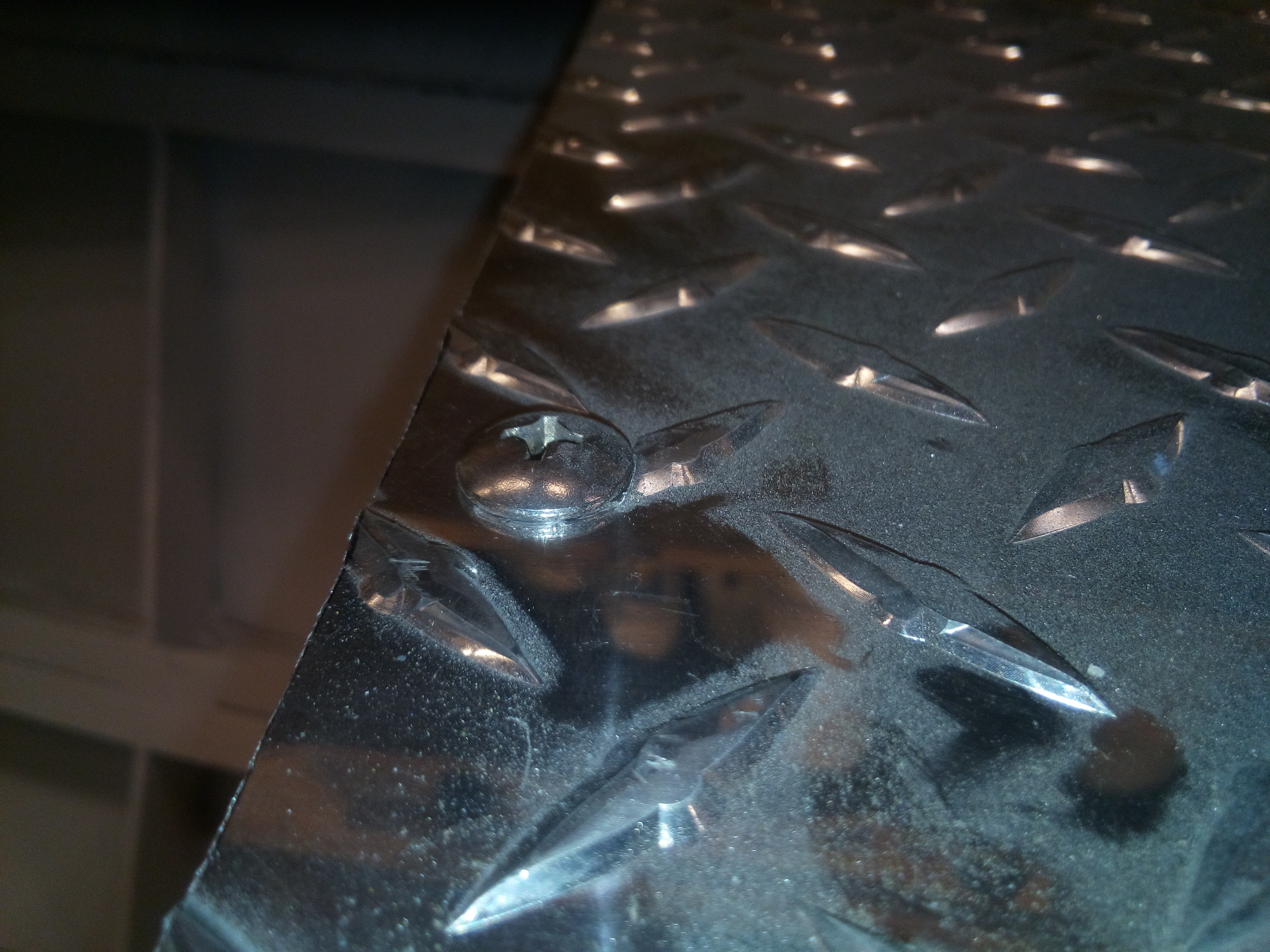
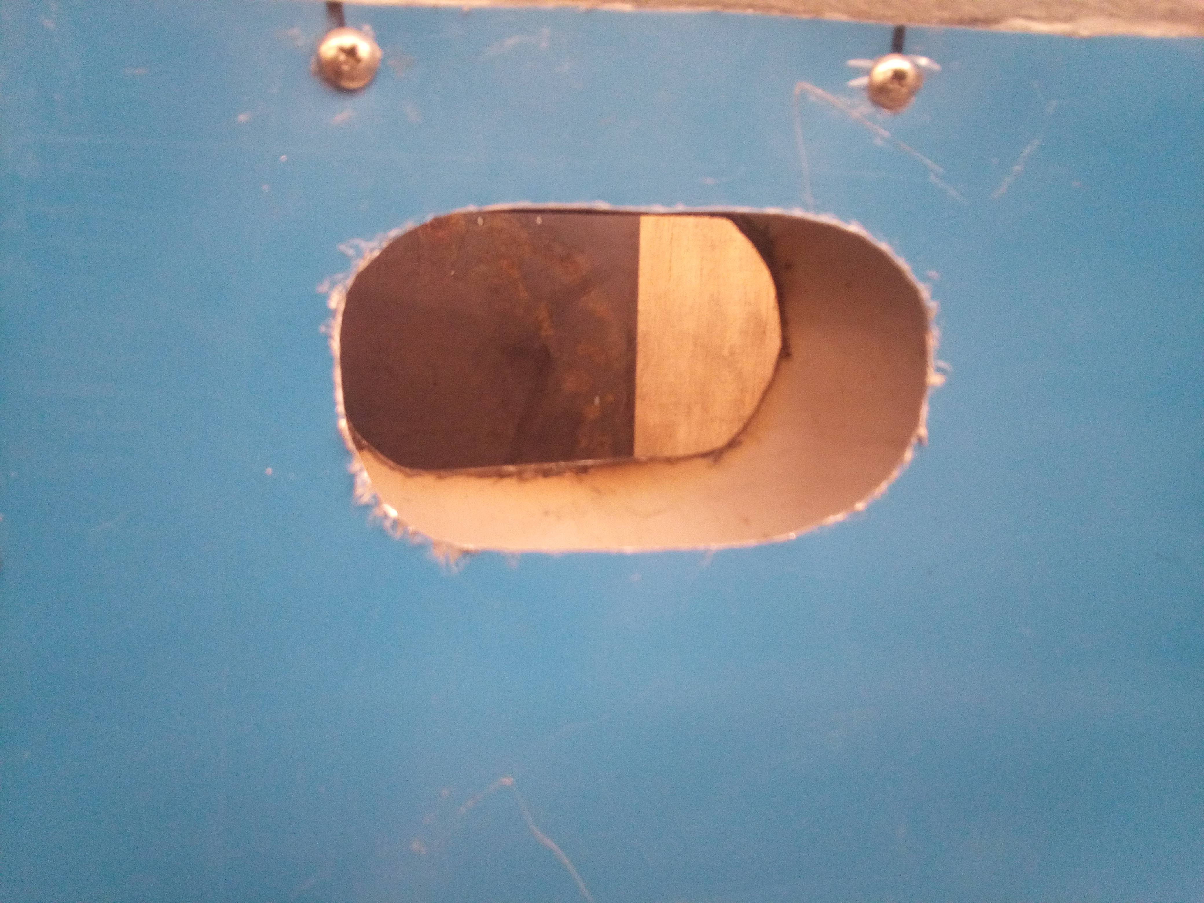
I installed the grab handles for the forward battery bank access hatches.
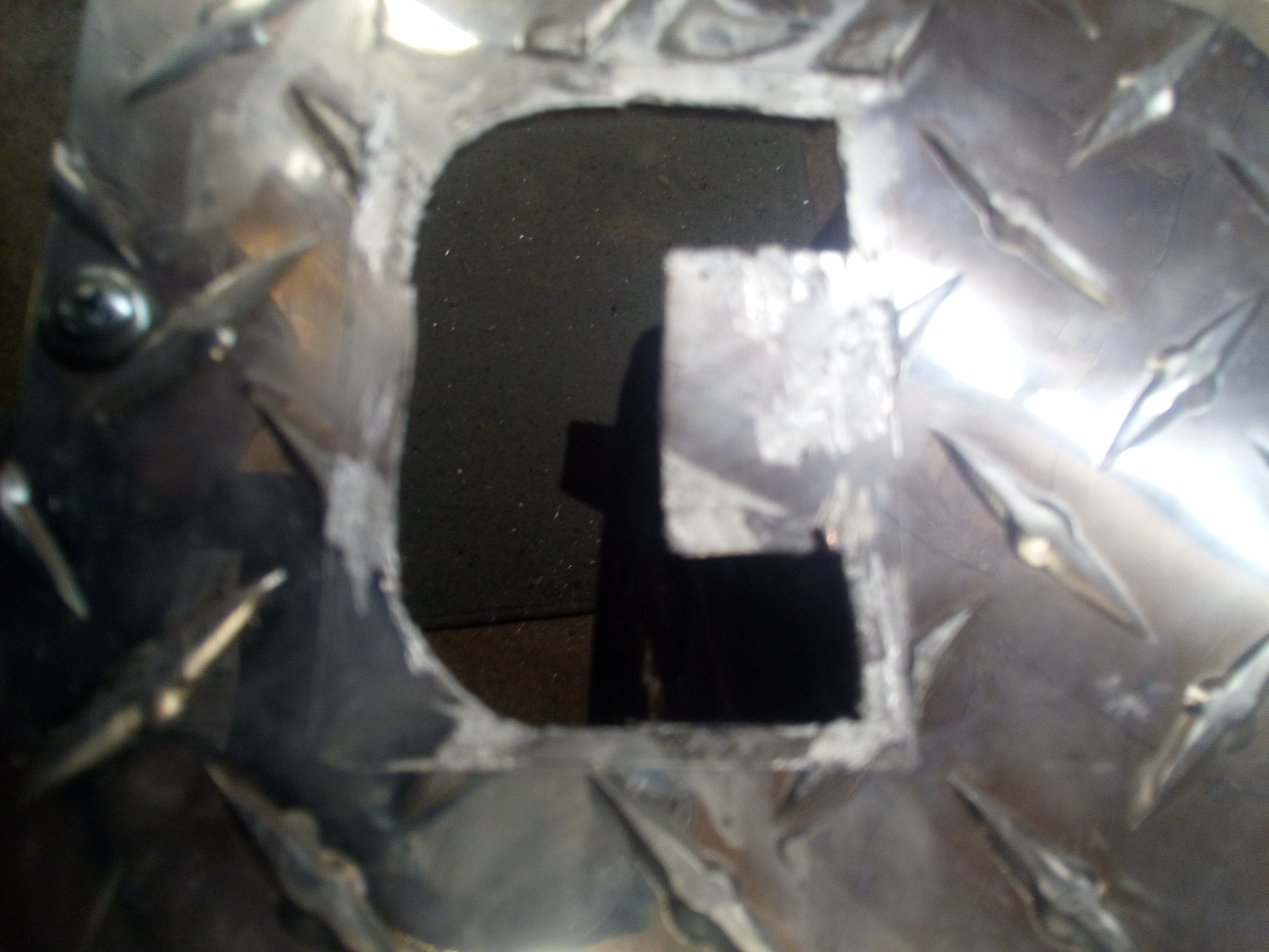
The hole doesn't have to be that pretty...
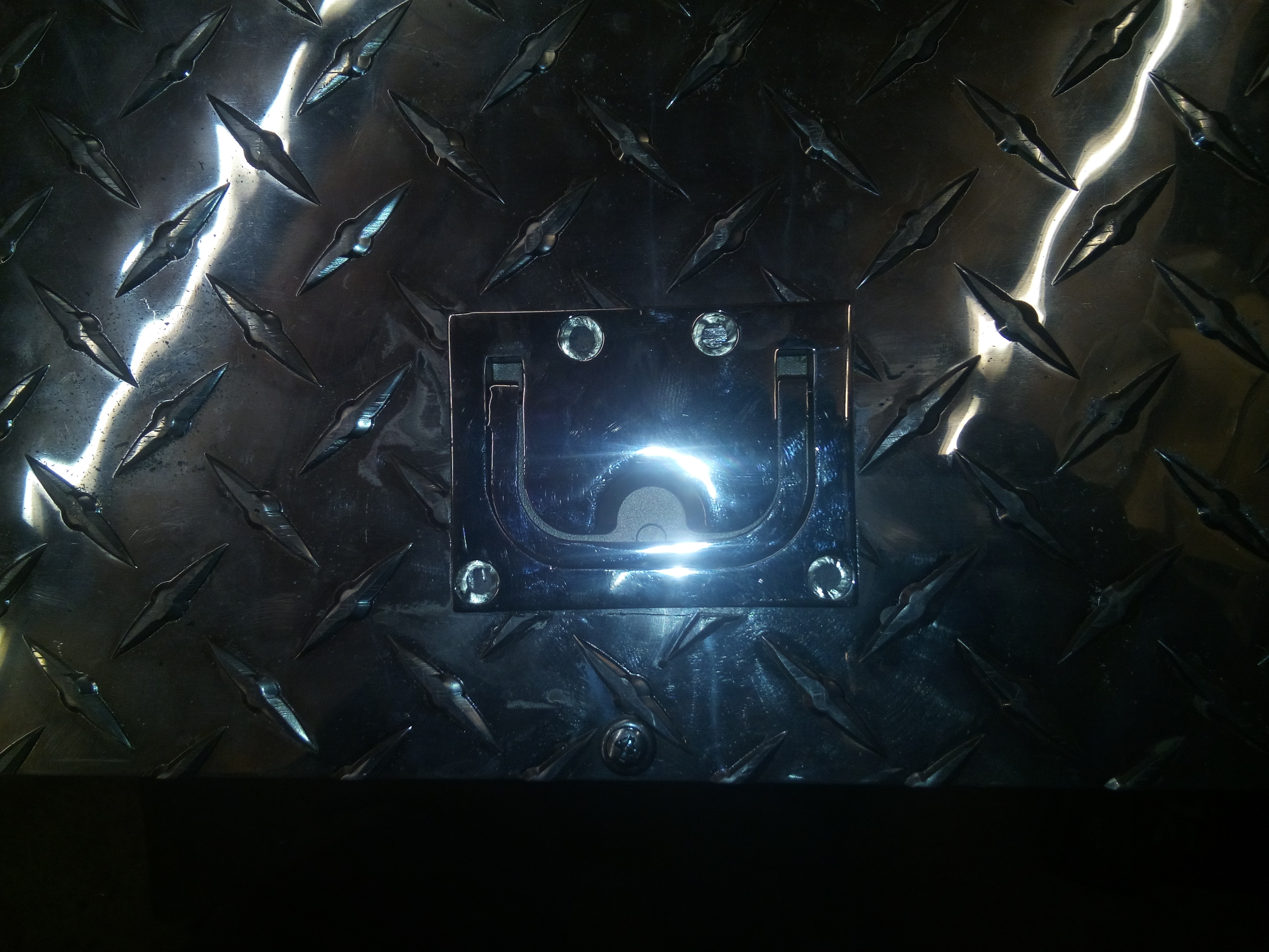
You just need to be able to cover the hole with the fixture...
I used duct tape to protect the shiney until I installed the handle.
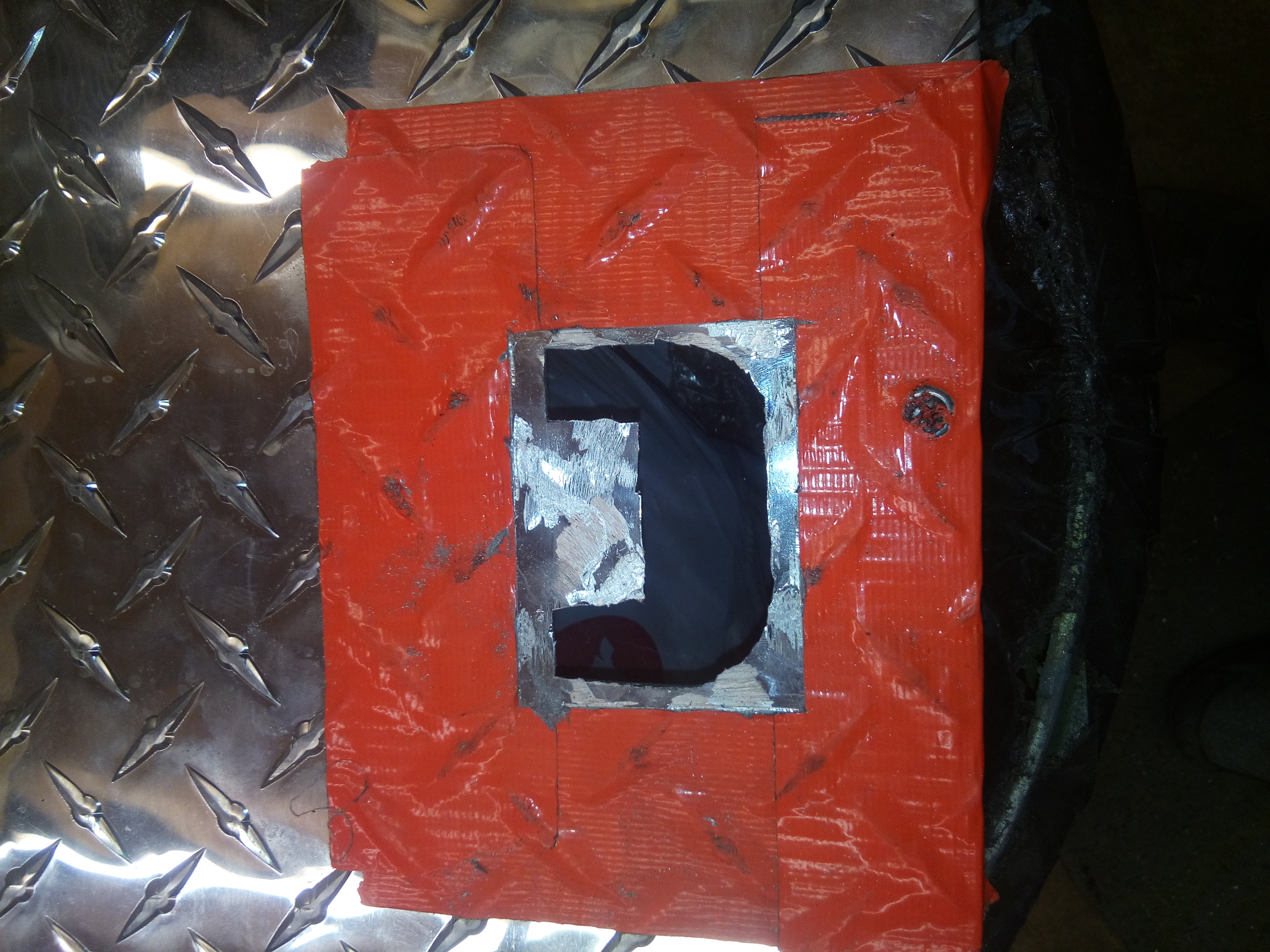
Always use protection...
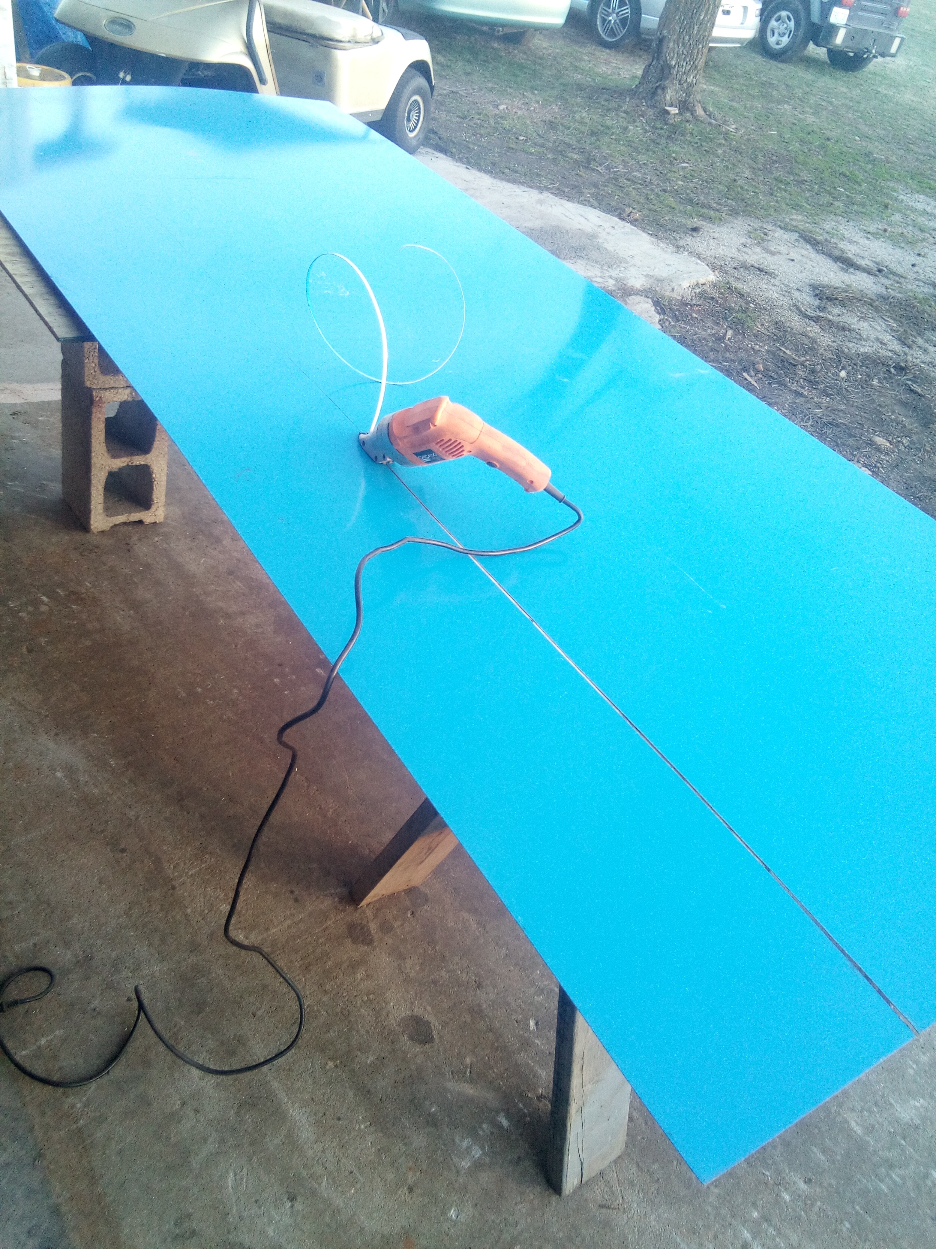
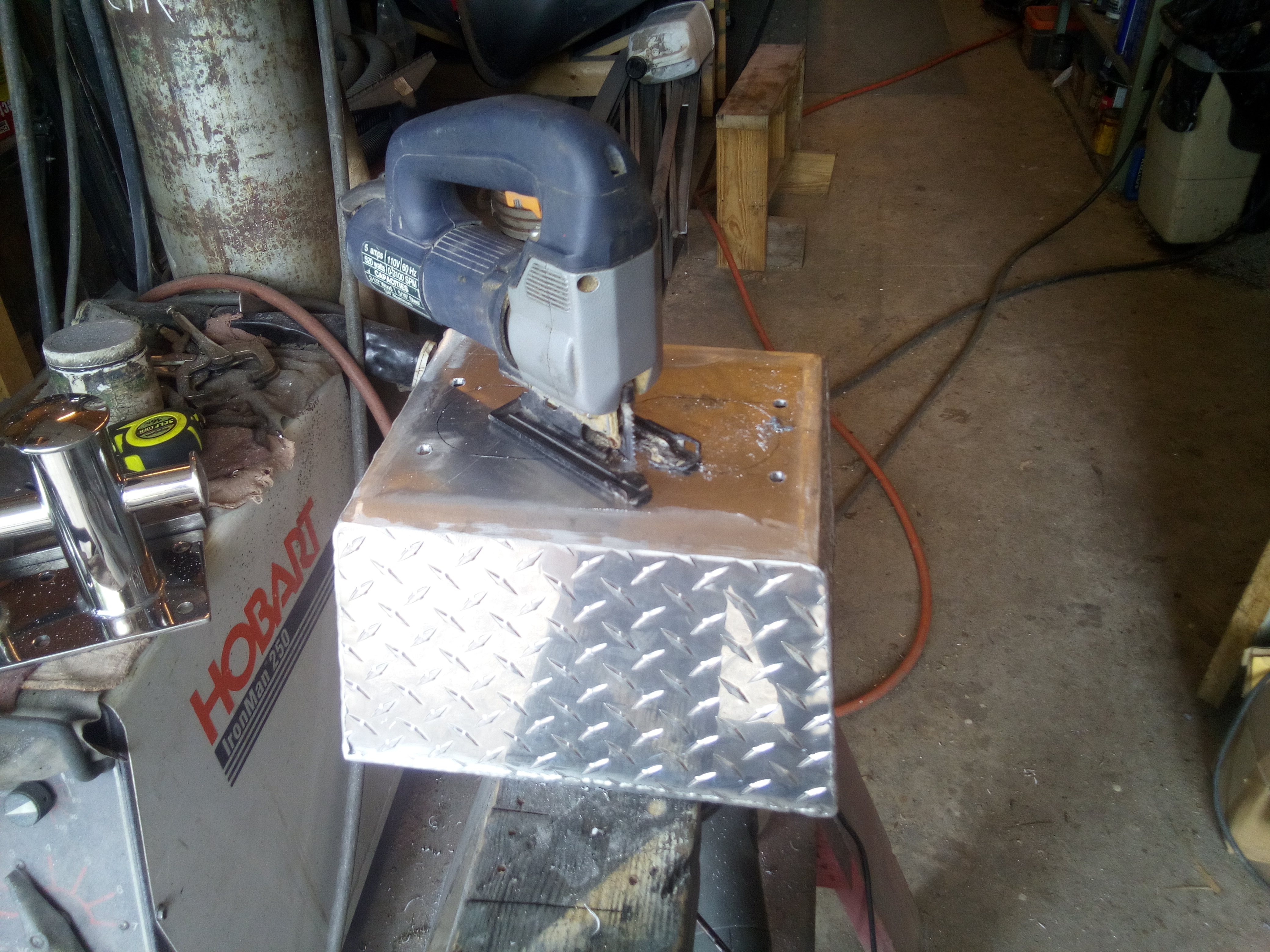
As I showed in the last entry, I cut out the raised fantail deck plate, but now with the painting all done, and the motor hatch bolted in place, I needed to mark and cut out the portion that was the hatch cover. I opted to have a small edge of the hatch skin to overlap onto the surround frame. This will help in preventing dust and particles from getting in the crack and working their way into the "purty" white bilges. So I clamped the rough skin in place as tight as I could and dressed and ground until it was the fit I wanted. Then with the hatch frame removed and the skin clamped down tight, it was a simple task to use a fine tipped marker and draw out the hole.
After removing the skin, I measured for my overlaps, straightened lines, and cut it with my little battery powered circular saw with a small metal cutting blade. Boy, what a mess of little metal chips it made in my shop!
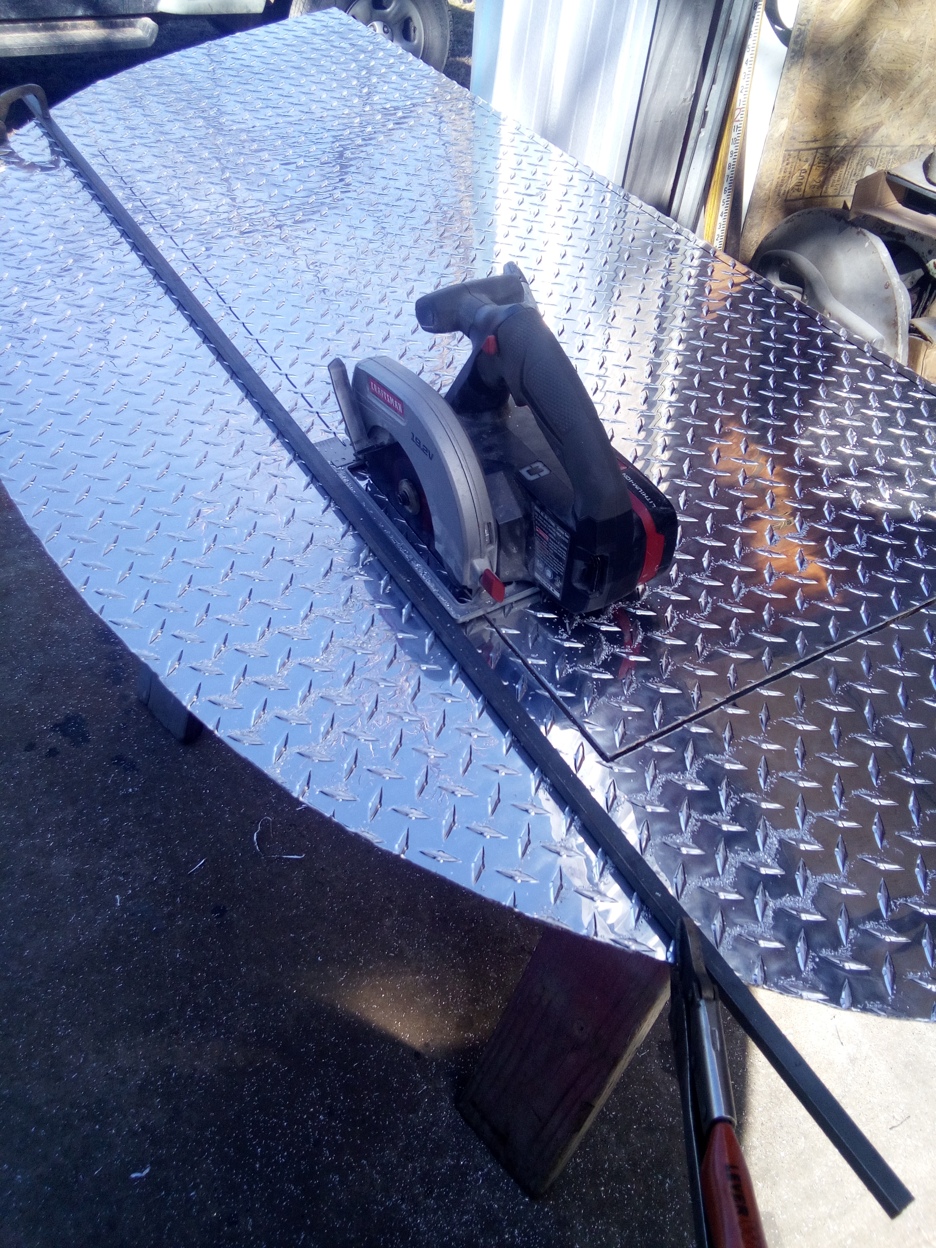
Hatch being cut out.
Then, with the wasted corners from cutting the fantail deck, I was able to cut out a couple of corner steps that go from the aft deck, to the raised side decks. Looked great.
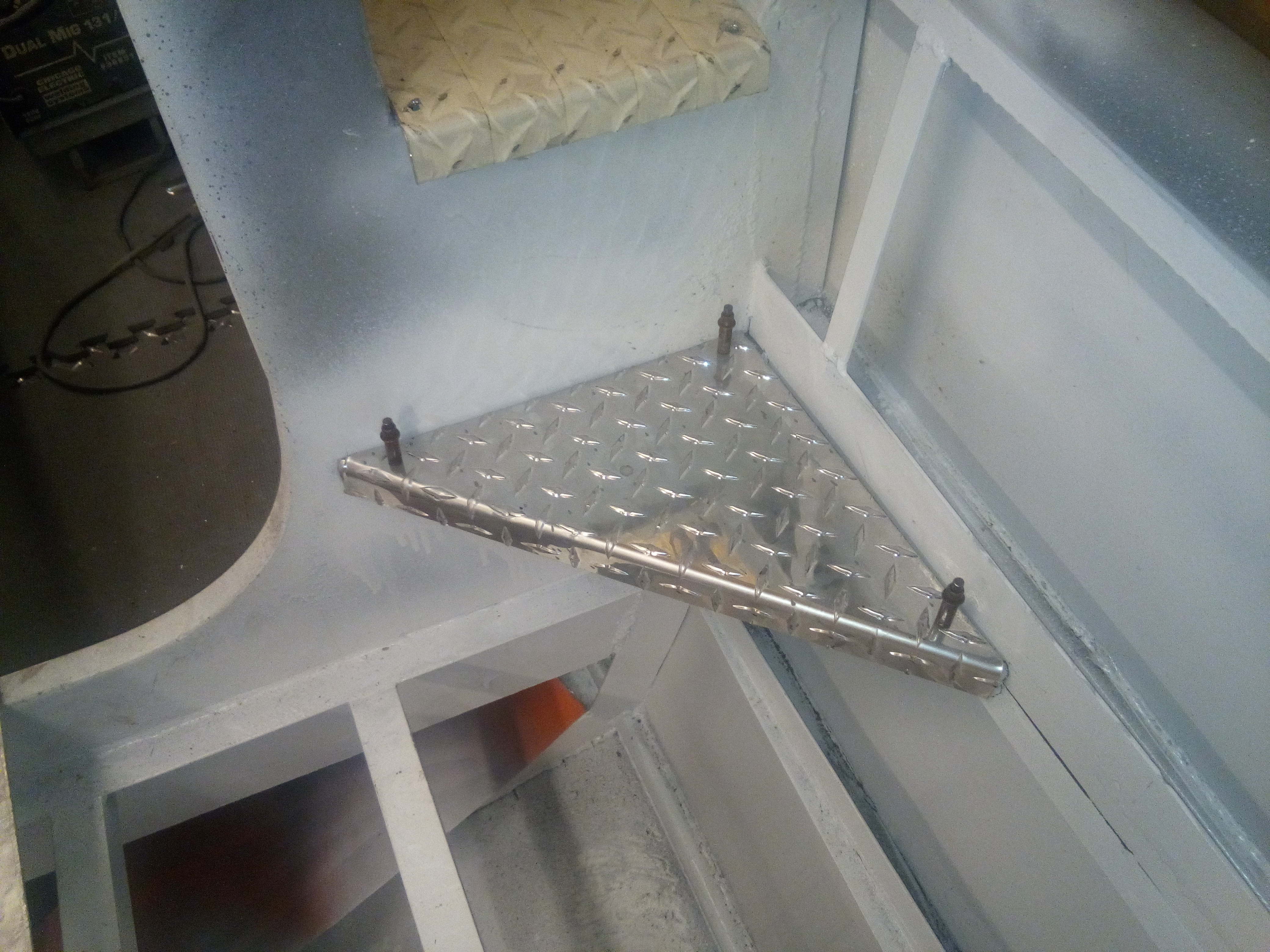
Corner steps from tread plate scraps.
From some of the other scraps, I made one side deck skin.
Starboard side deck, covered in masking tape prior to bolting down.
Then I used my small supply of clecos and started drilling and clamping stuff down.
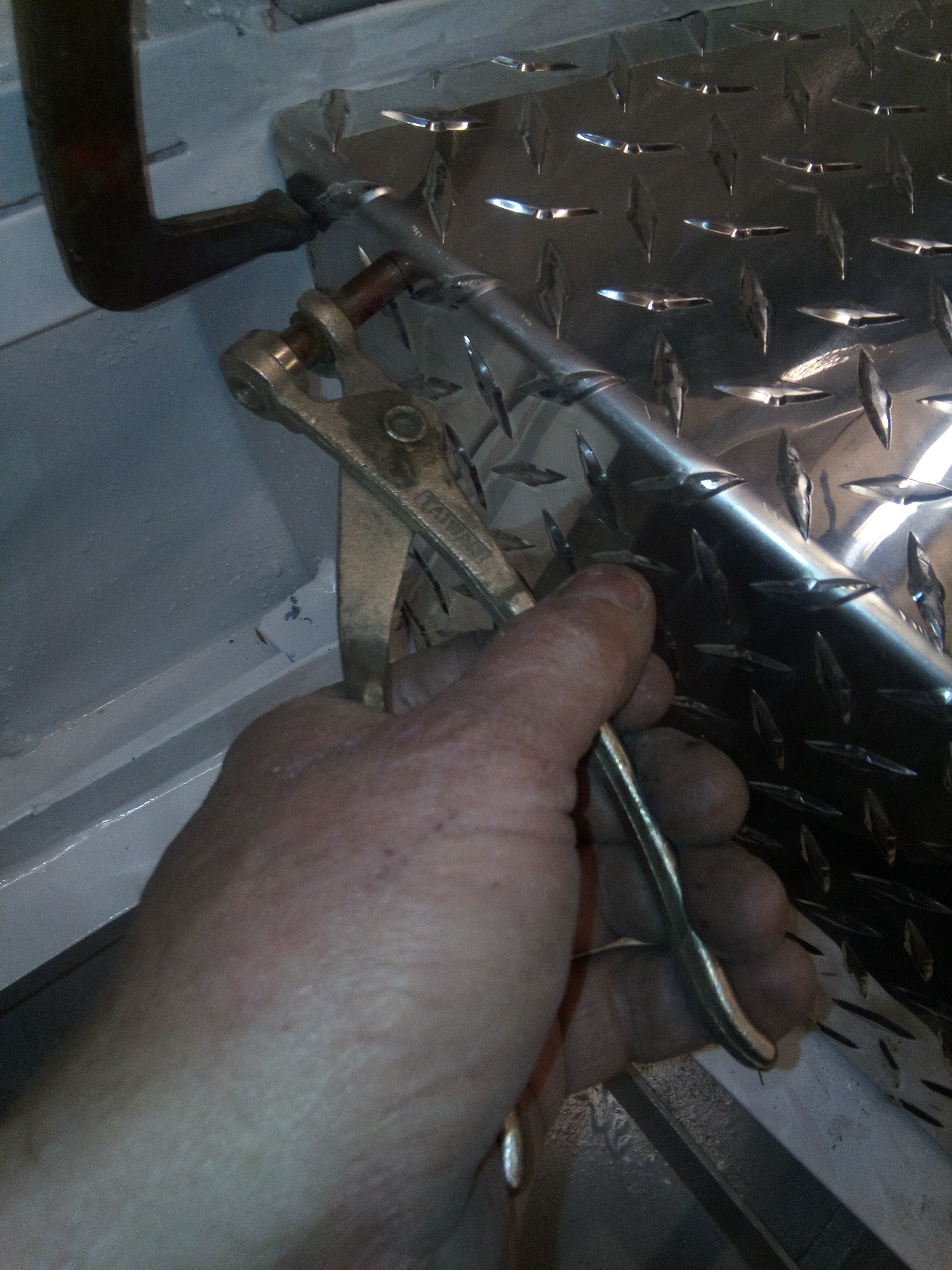
securing the decks with clecos
fantail deck all clecoed, ready for deburring and counterboring.
I forgot to mention, the clecos are from the aviation industry, and work well at holding panels until all the holes are piloted. They aren't expensive, and can be had from places like Aircraft Spruce & Specialty in Fullerton, California. Then you need to get a counterbore bit for taking off part of the raised treads where the screws go. I bought a used, dull one on eBay for $10. It needs to be slightly larger than the head diameter of the screw or bolt you will be using. In this case, 9/16" hand bit.
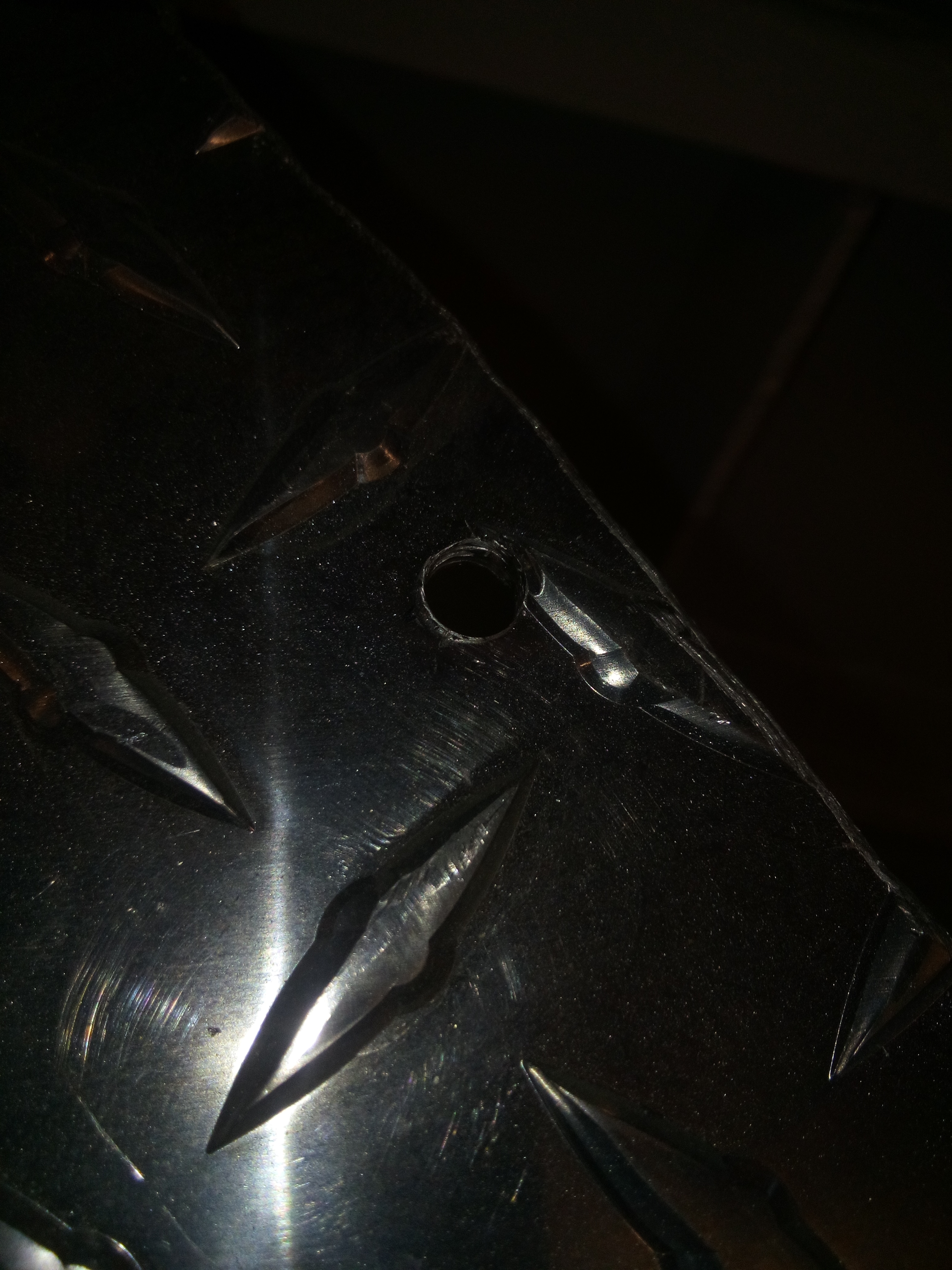
Deck screw hole before counterboring.
... After counterboring.
Looks and works a lot smoother.
As I have mentioned, I also deviated from the plan, by replacing the "love-bench" around the fantail, and adding interior panels to the insides. This increased the deck area quite a bit. They are .040 aluminum skins with a factory paint and protective plastic skin on both sides. This makes them a finished thickness of .044". I will leave the protective plastic coating on the inside, but will peel it from the outside just prior to first launch. The local steel shop sells these in a 4' x 10' size. I cut a couple of 12" strip, slightly over-sized skins for the upper-innards.
Roughing out the inner side skins.
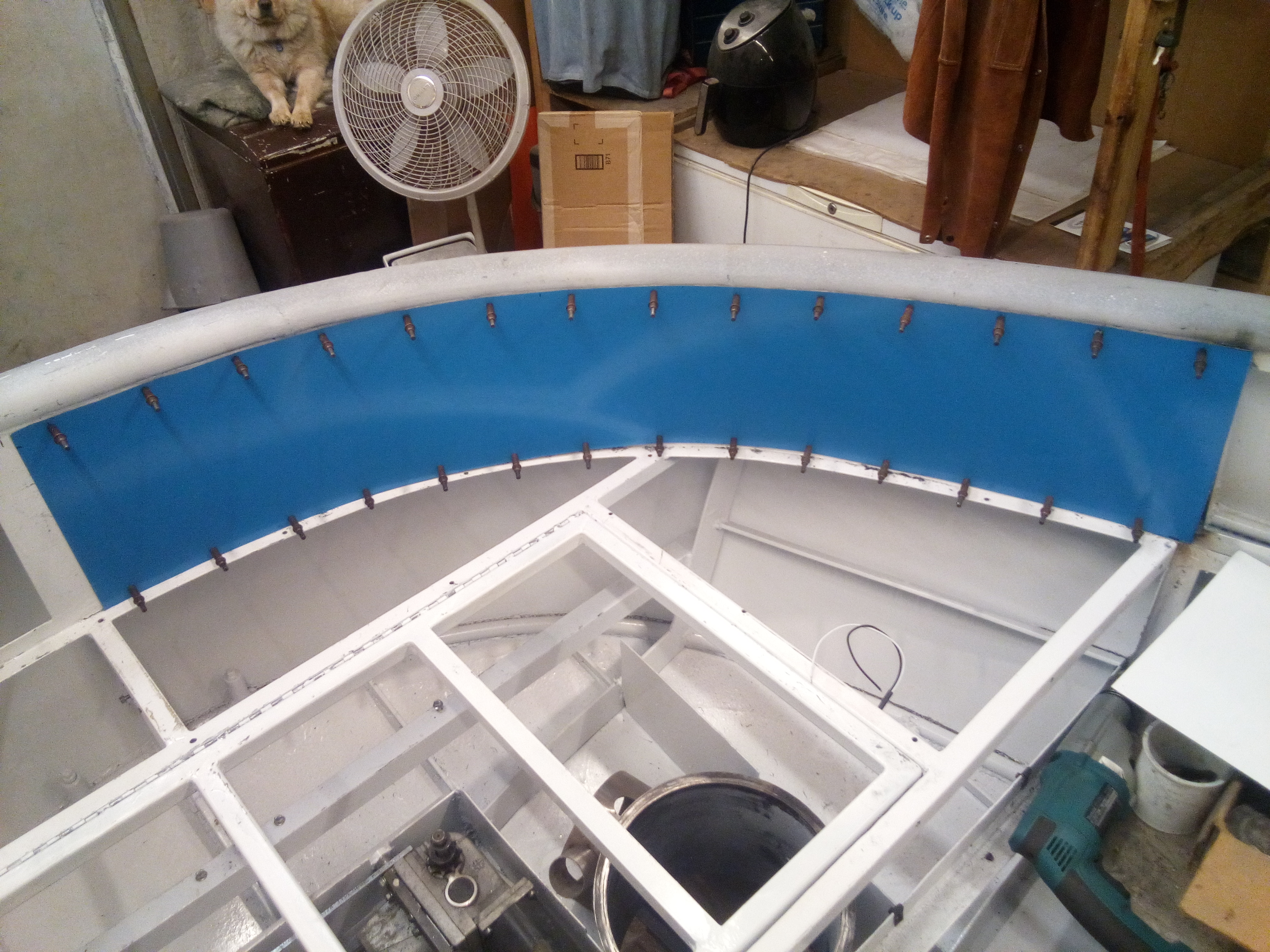
Fitting the aft inner side skins.
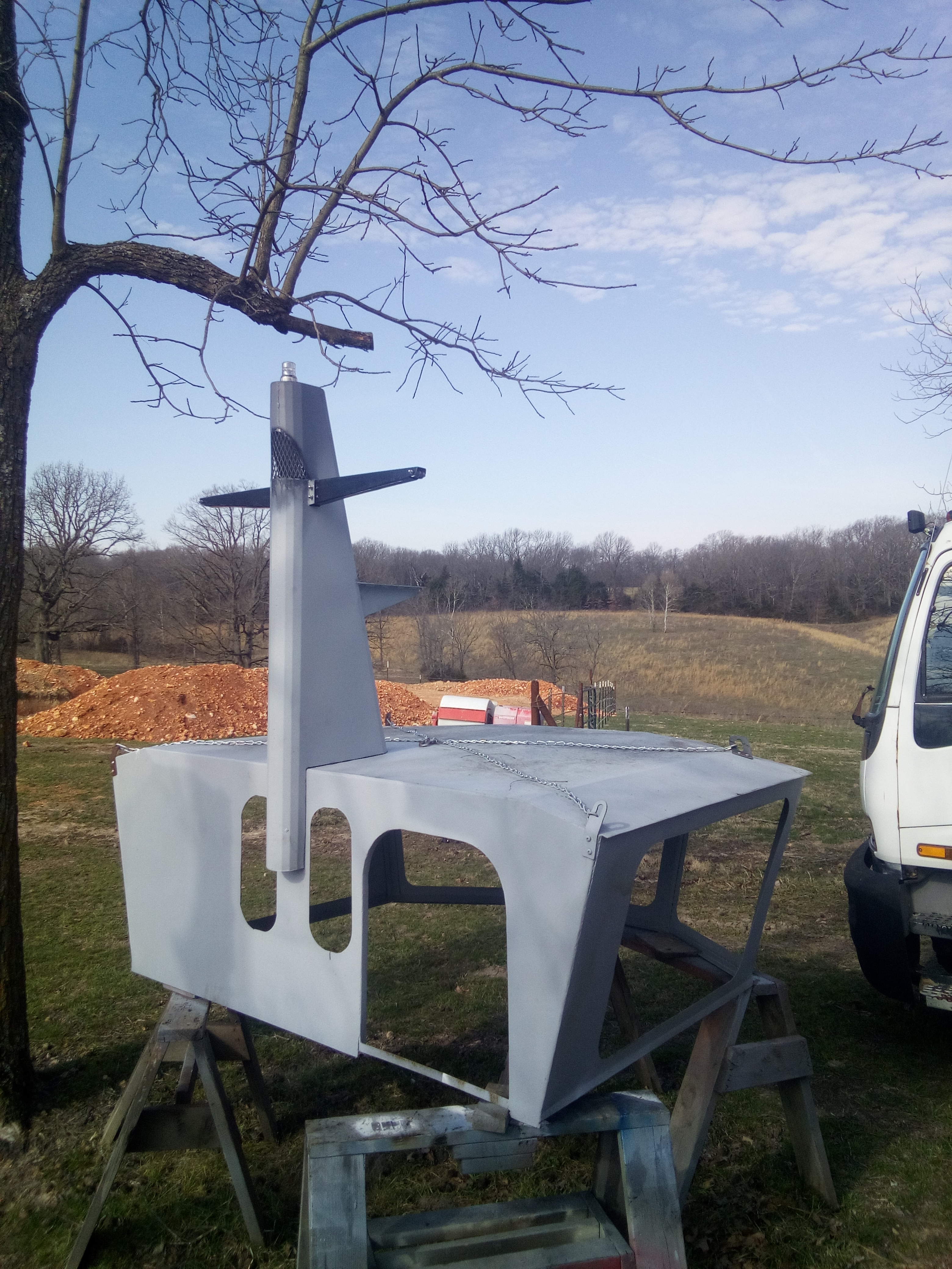
I also built a cooling tank to mount my main drive controllers on. It is a design that I learned should keep the 500 AMP controllers cool enough to meet the mission goals.
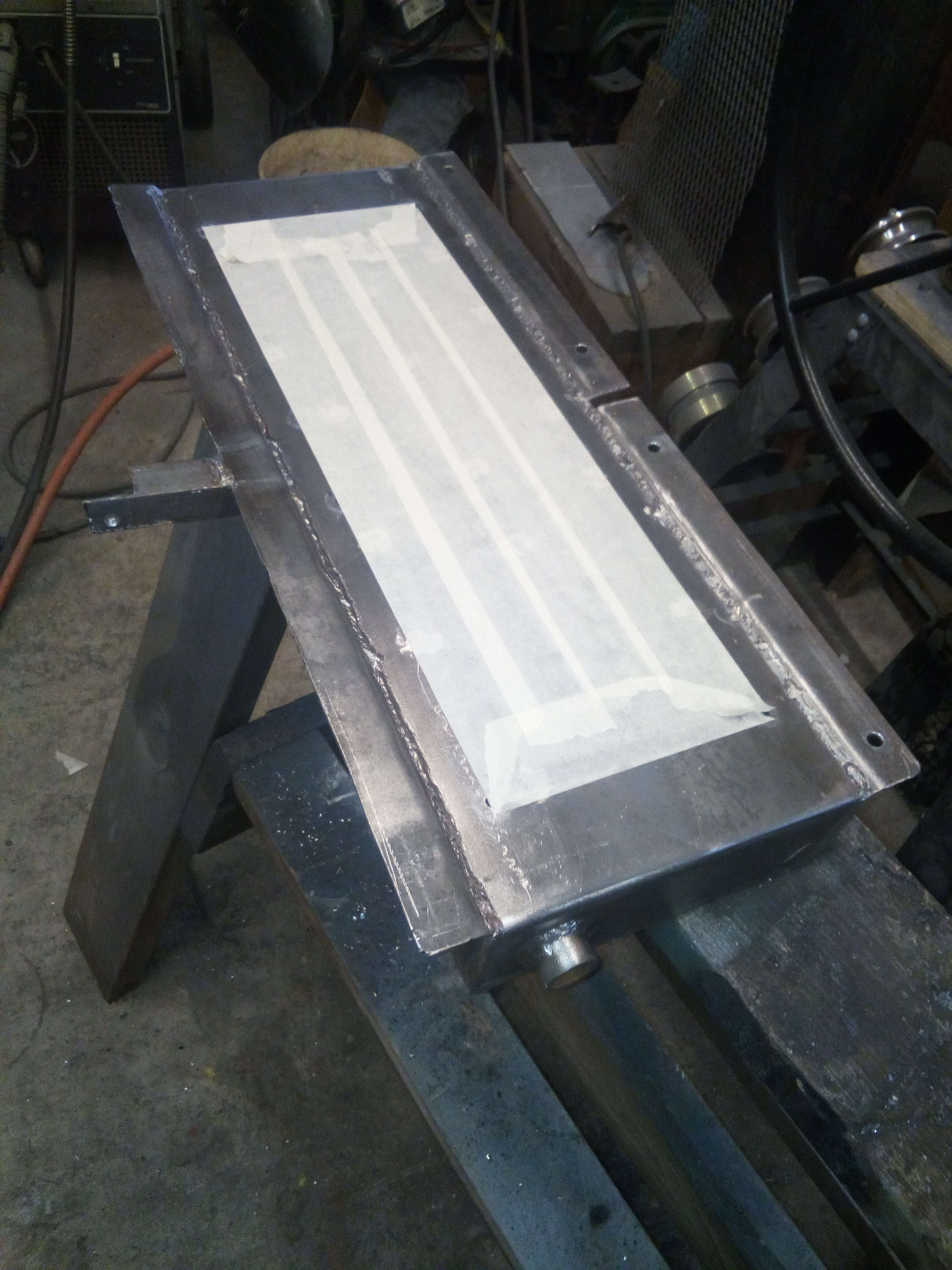
controller cooling tank, built and ready for paint.
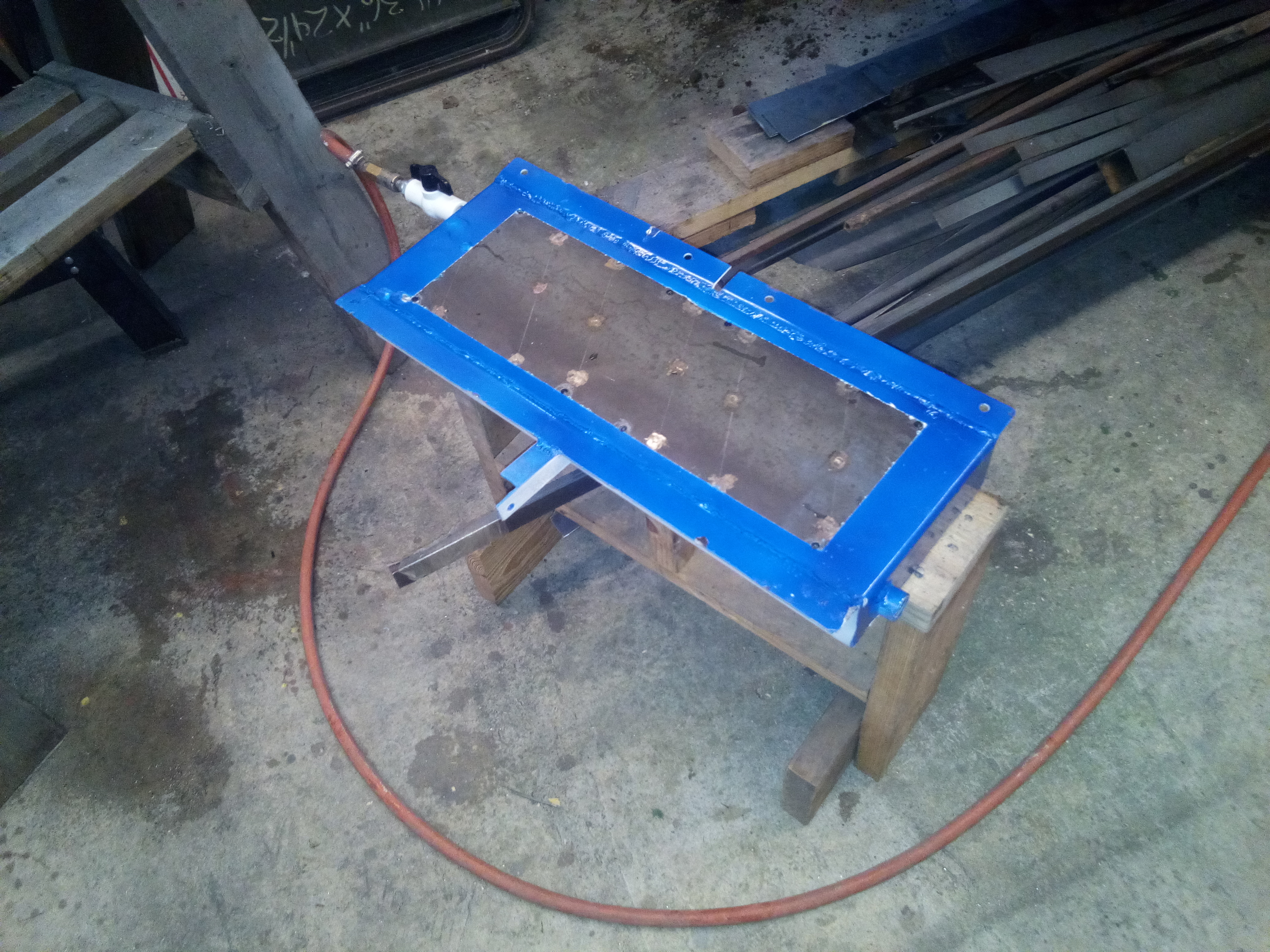
Painted, ready for pressure testing, ... it failed badly. Needs to be seal sloshed.
It will be connected to the chine cooler with a small marine pump. Since the pump and tank sloshing compound are in transit, I will include a picture of the completed system next month.
I had to add some backing plates to reinforce the locations for the deck cleats.
supports for aft quarter cleats.
Aft twin bollard supports. all supports are 1/8th"
In an effort to reduce the loose hardware, I decided to use "J-nuts" and "nut-serts" or "riv-nuts" to secure the deck plating to the framework. This lead me to get yet another tool I have wanted for years. I'll include a picture of that soon. Here is a shot of the nuts in place but not set. I am also including in the build, LED white courtesy lights in key locations like the motor bay, the battery bays, the generator bays, and the forward anchor rope locker and the charger bay.
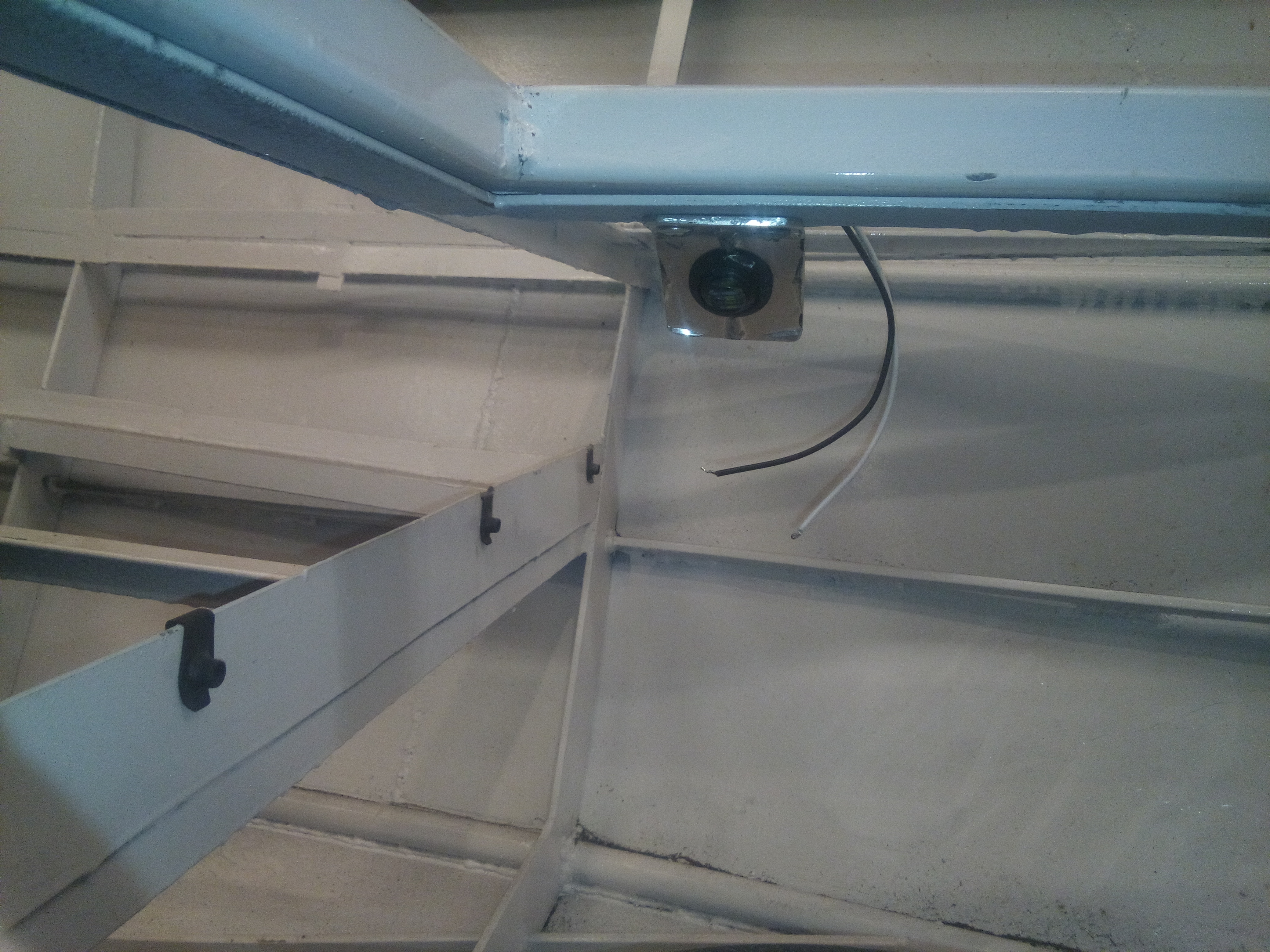
Riv-nuts, J-nuts, & LED courtesy lighting in key locations.
The holes are starting to get filled on the center panel. wiring will follow, ... Just have to eat the elephant one bite at a time.
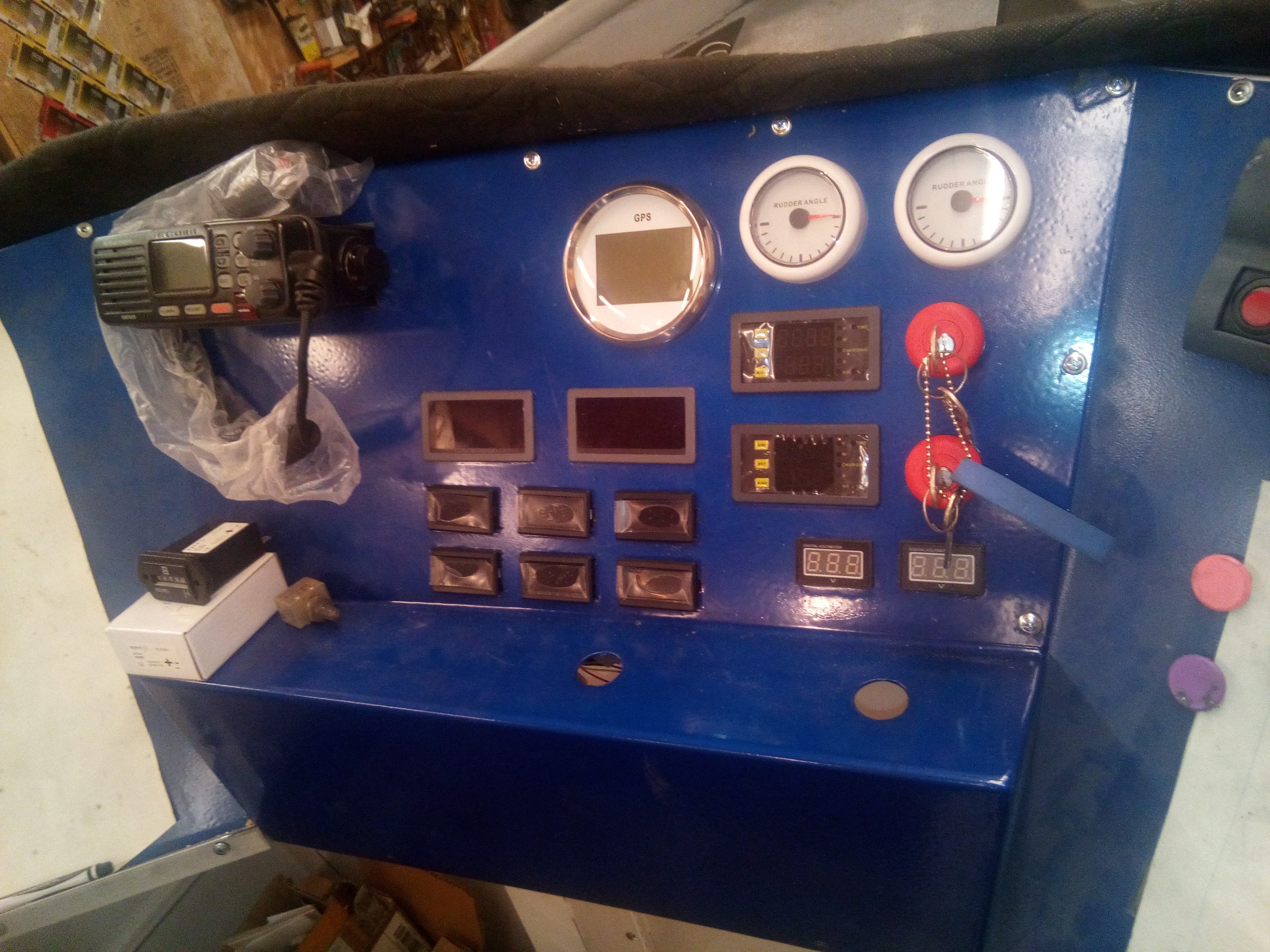
That is twin everything +GPS speed, VHF, and a half-dozen system temp gauges. (75% complete)
So many circuits...
One thing about building a potentially commercial project is, the additional rules that might sneak up on you. So, last Friday, I contacted my closest US Coast Guard to do an inspection, before I get it all closed up. They are quick to follow up and offer advice and information of a safety nature, that me the builder might have not found in other ways. More on this step next time.
For those that have been such a fantastic support in the breaking and shearing, I really need to mention my local metals fab shop. The owner, Mark Volenweider, and his sheetmetal man, Morgan, have been indispensable in getting the stuff done that I could not afford the machines to do. I would suggest that anyone deciding to build something like this look for, and fine a really well equipped shop like Mark's. My guess is, that he could do this build in a fourth the time. But then I would have never had so much fun...
-
Insight for those thinking to build a boat -
It is amazing how perceptions change over the course of the build. It seems that the masses that first told me that it wouldn't float, or that I could not do it, are rapidly changing their tune, and some are even hailing this as "an amazing build". My strongest advice to anyone that wants to build a boat, any boat, is to ignore any and all people that are negative about it. These are the "armchair" professionals that will never do anything of value in their lives. I still have "technical experts" in one field or another, that even as recent as last weekend, insist that I am doing it all wrong, that it won't work. I believe these same folks have probably never descended to their knees, and asked for Divine assistance. These same folks know nothing of what the would-be builder goes through, how they grow as they progress in the construction of these boats, metal, glass, or wood.
My advice to anybody who is intrigued by the thought of creating their own "one-of-a-kind" would be, Do it! Just do it! I can say unequivocally, that it will be the most exciting, best learning, and nearly the most satisfying thing they have ever done. and when it is all done, no matter the quality of the finish, you can say with great self-esteem, "Look what God helped me make!" The amount of quality experience is rarely matched.
So until next time, keep the noisey side up. &&&&&&&&&&&&&&&&&&&&&&&&&&
29 April, 2018-
I am sorry for the late update, but the Spring operations of the farm took a front seat this month.
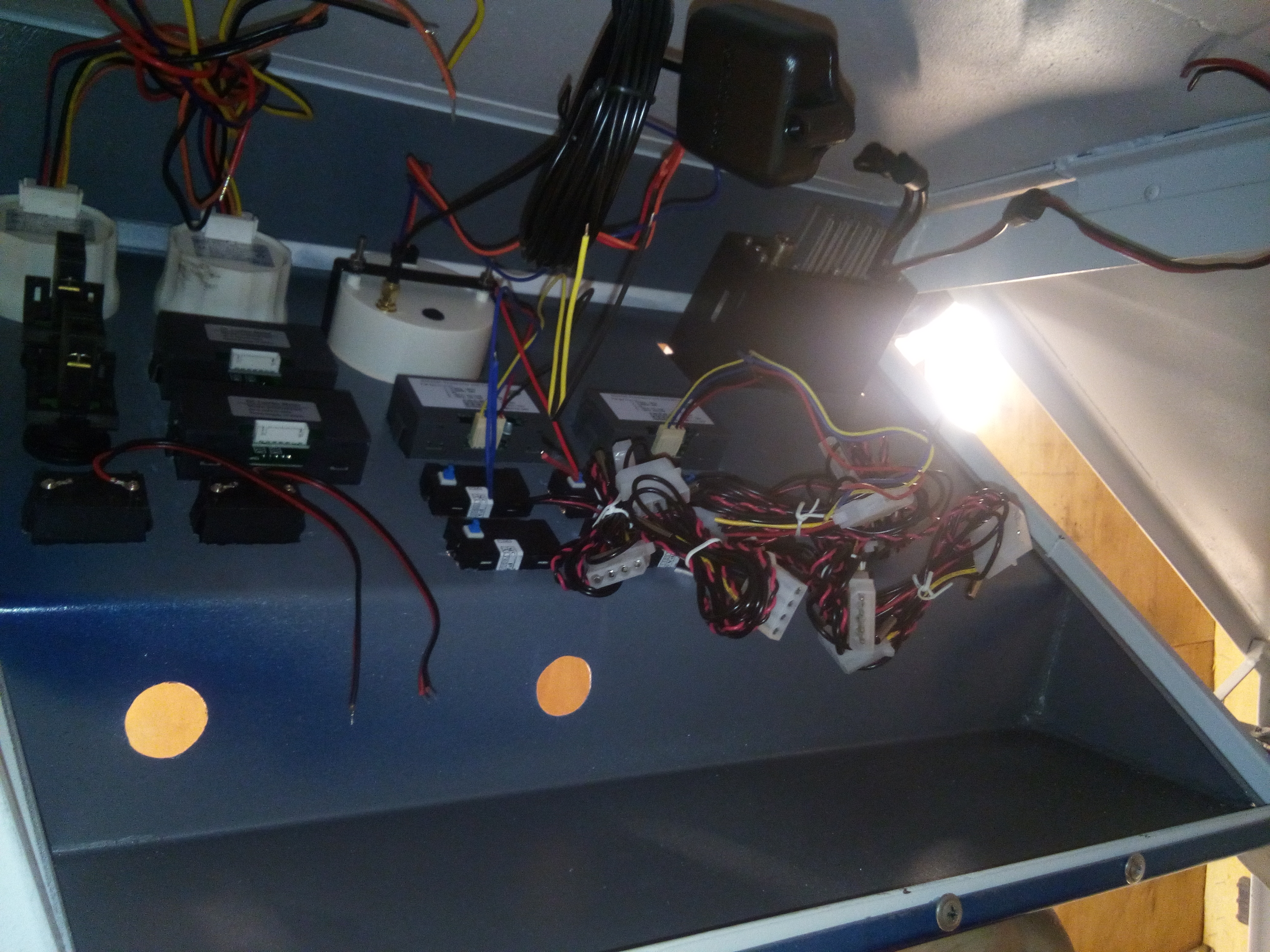
So I finished doing "make-ups" of the motor bay area lighting circuits, but not the home run to the buss bar.
Then I finished the component install of the controllers for the drive motors and steering motors.
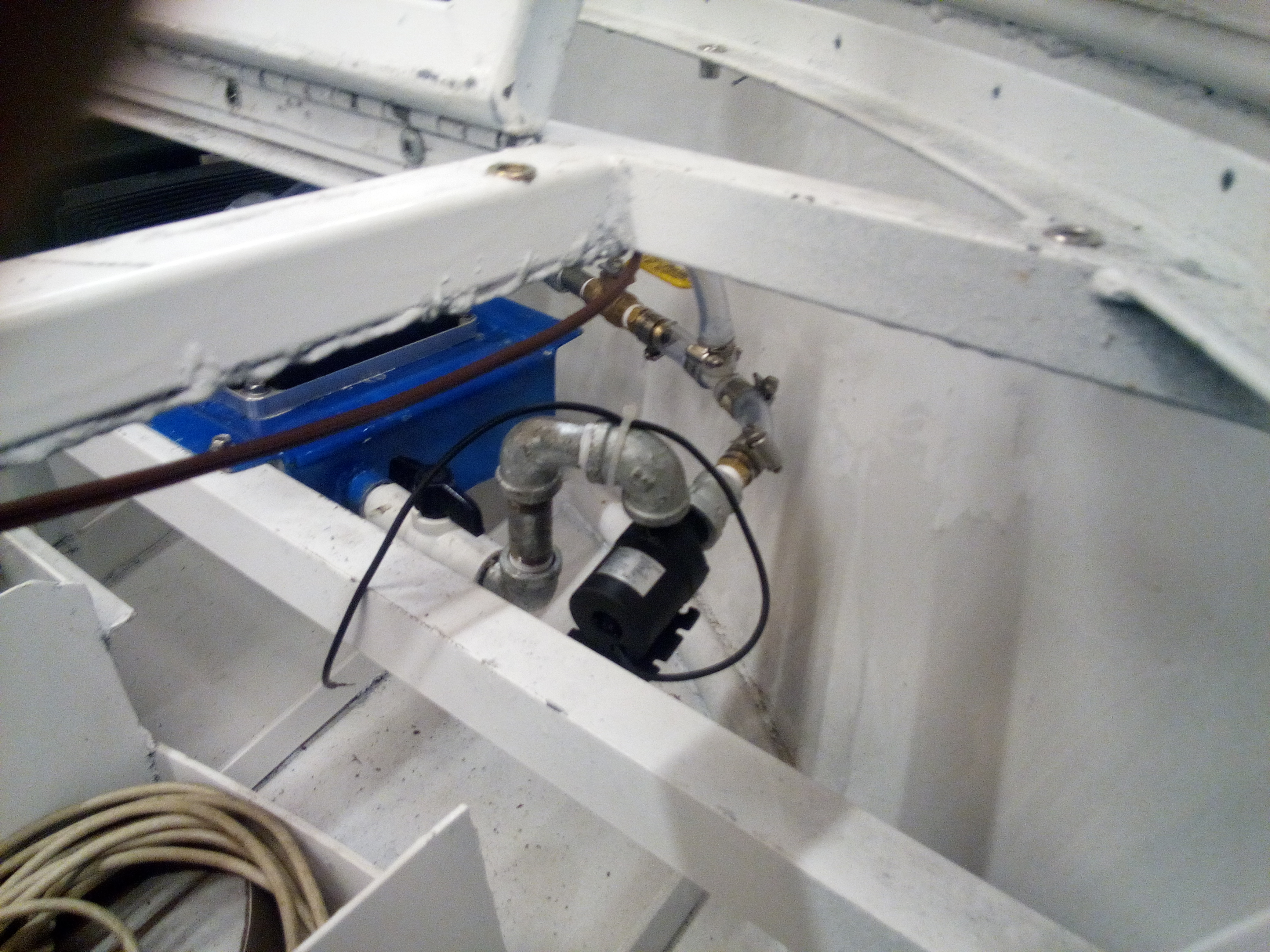
Pump installed.
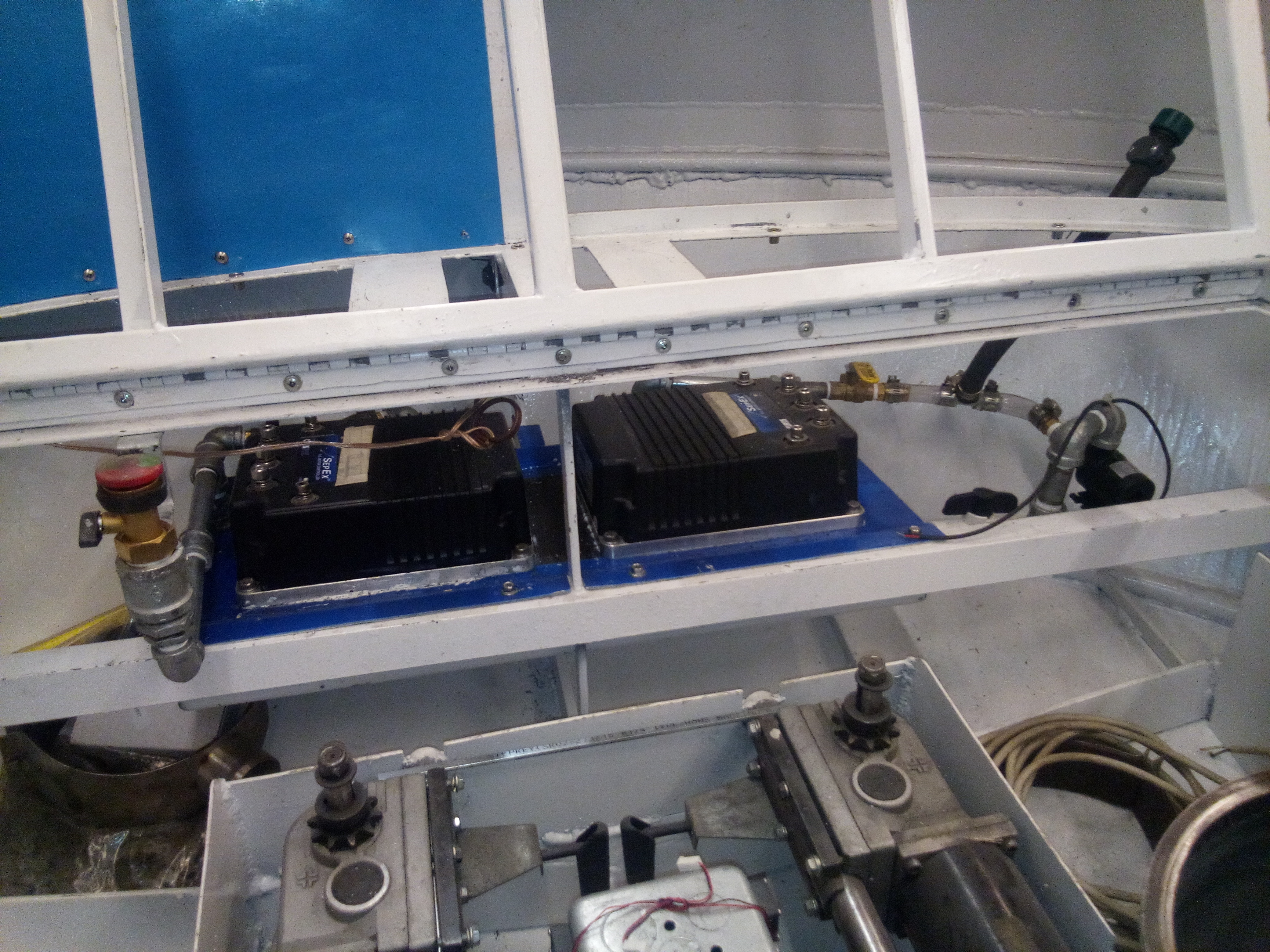
Drive controllers in place.
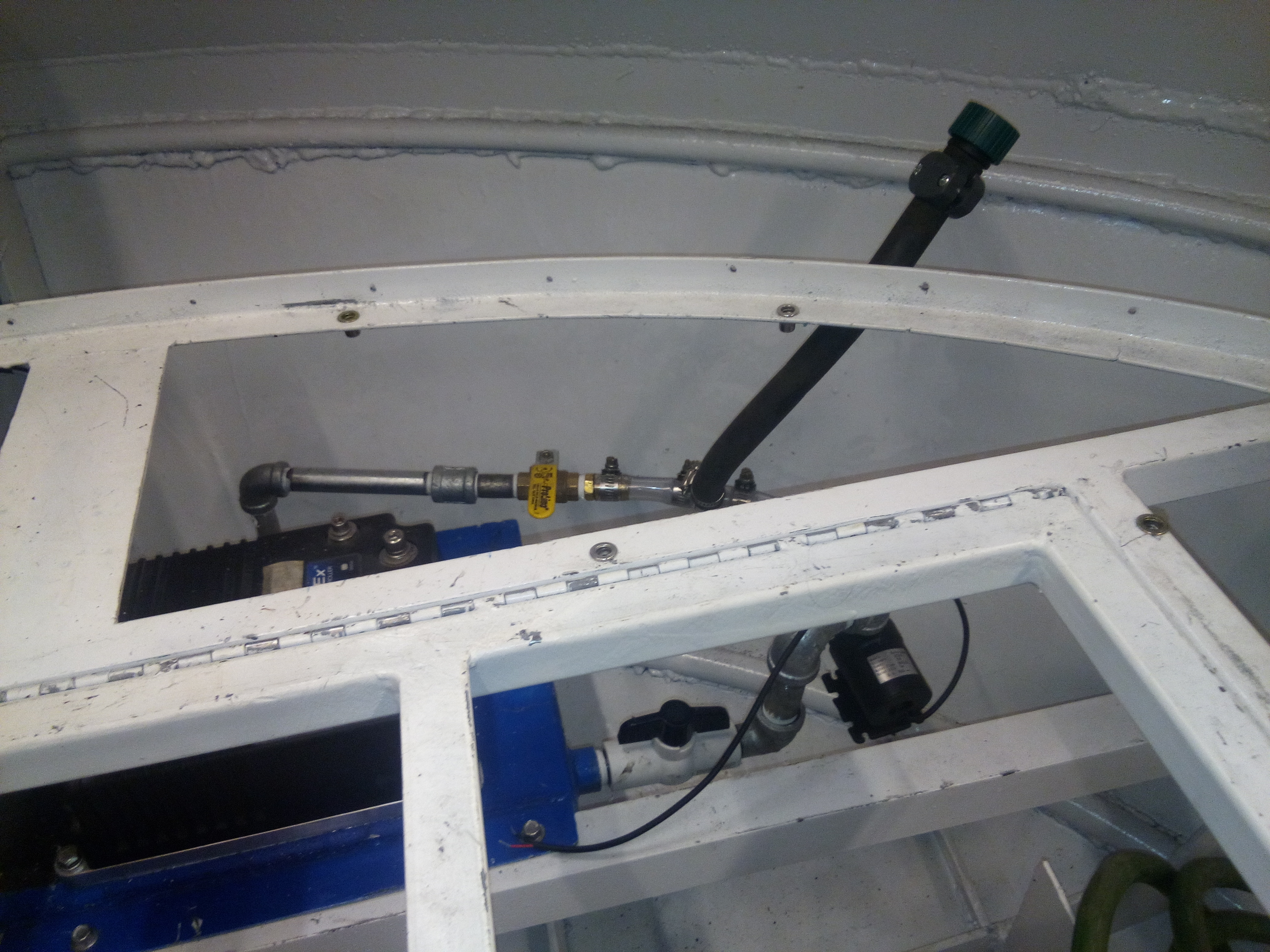
Outlet hose line for flushing.
I also finished the install of the chine cooling system with the fillers and valves for service and the circulation pump.
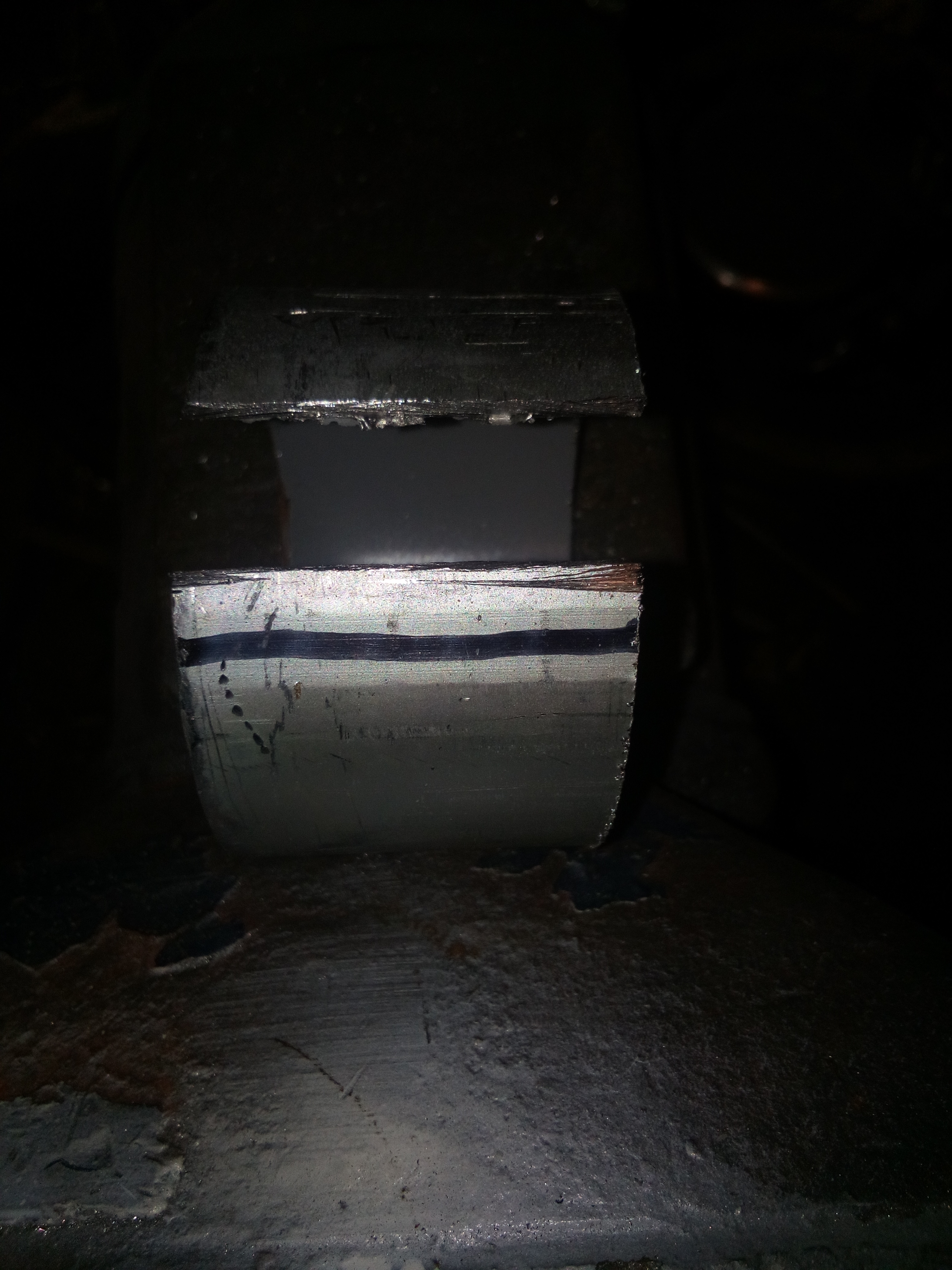
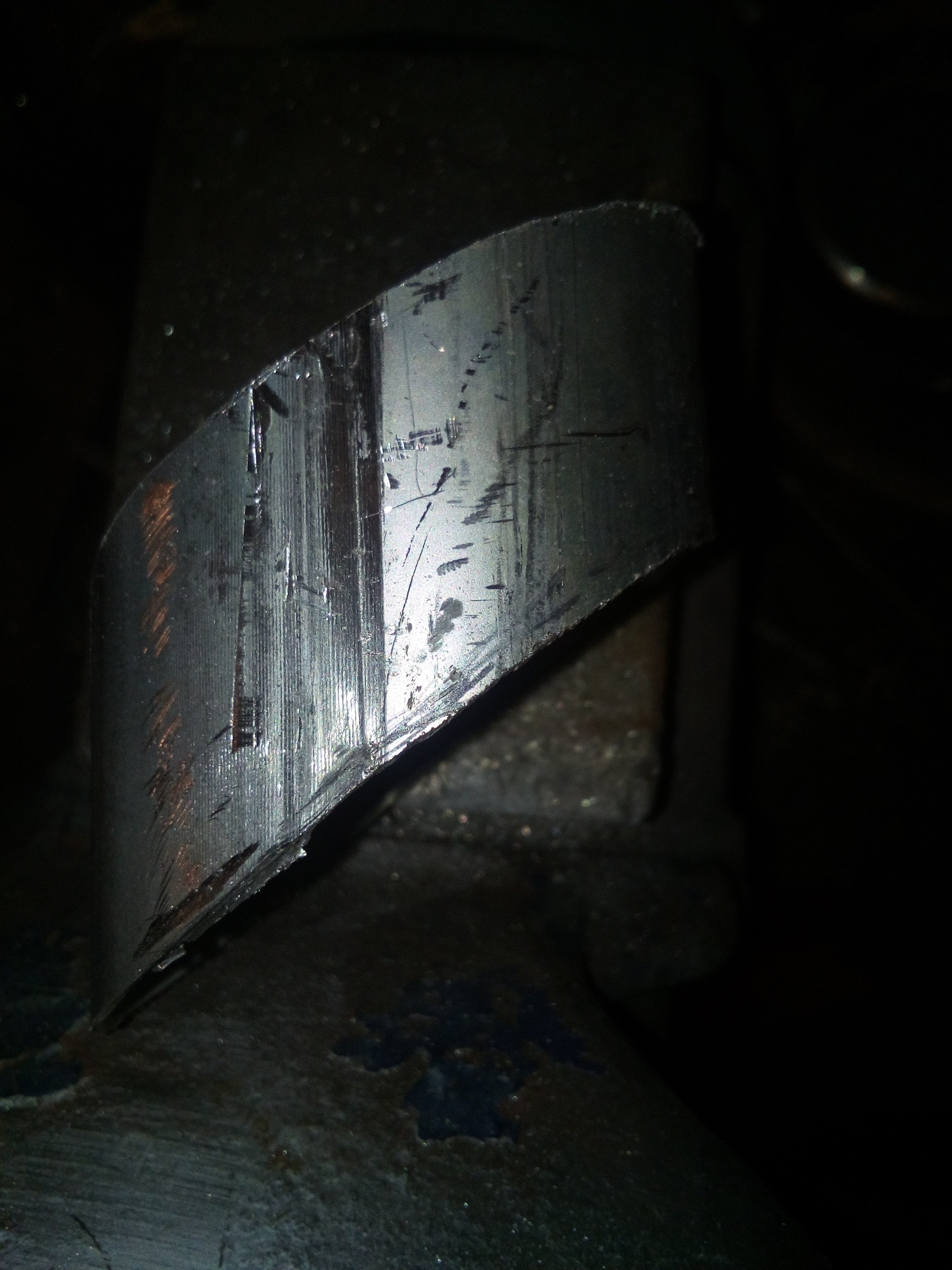
I started working on a stainless VHF antenna mount that needed a smaller mounting base. That needed to be welded and then the weld filed down to the surrounding level before cutting the sides off, re-drilling and countersinking the mounting holes.
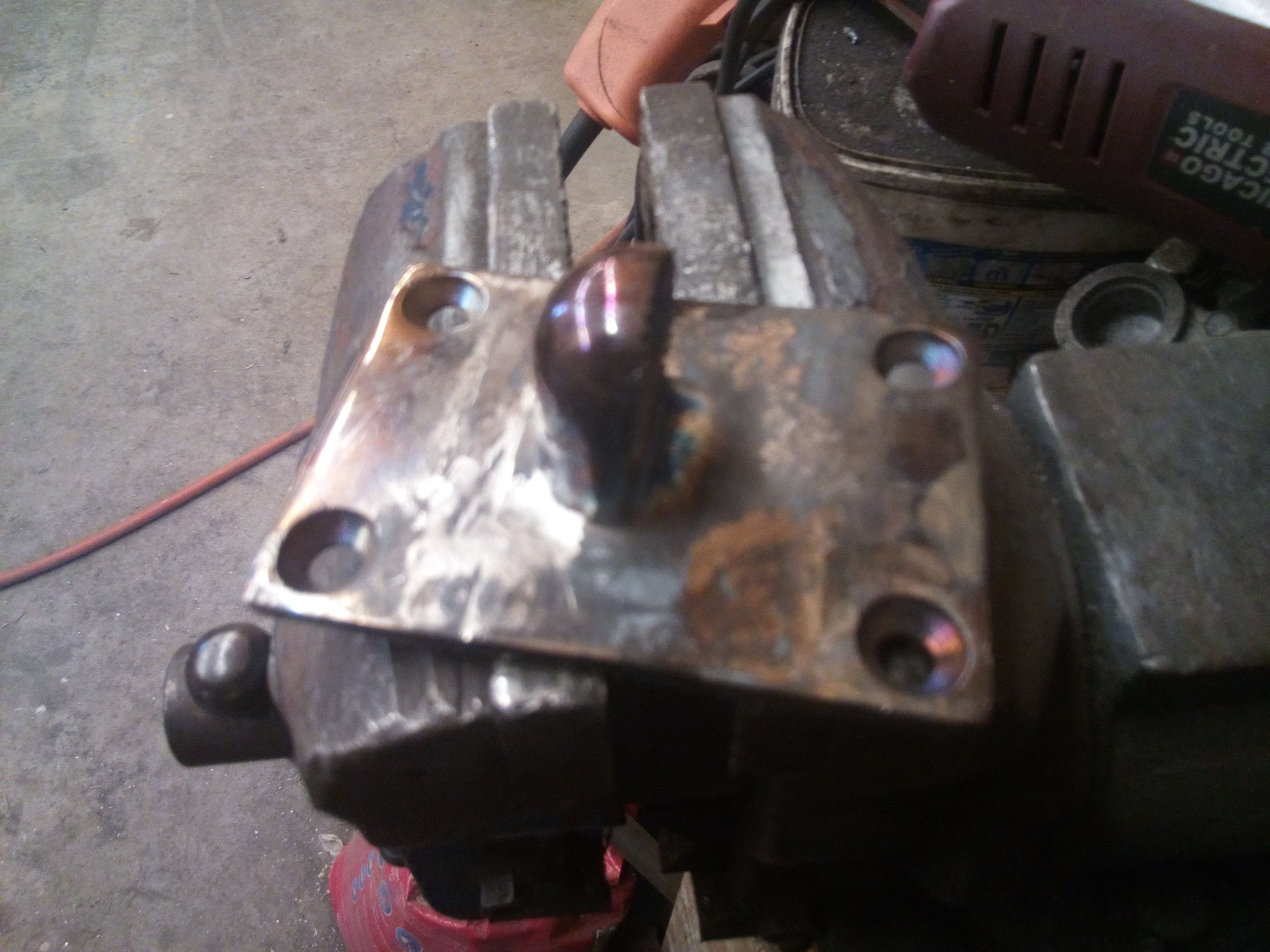
Discoloured VHF Antenna swivel base after welding.
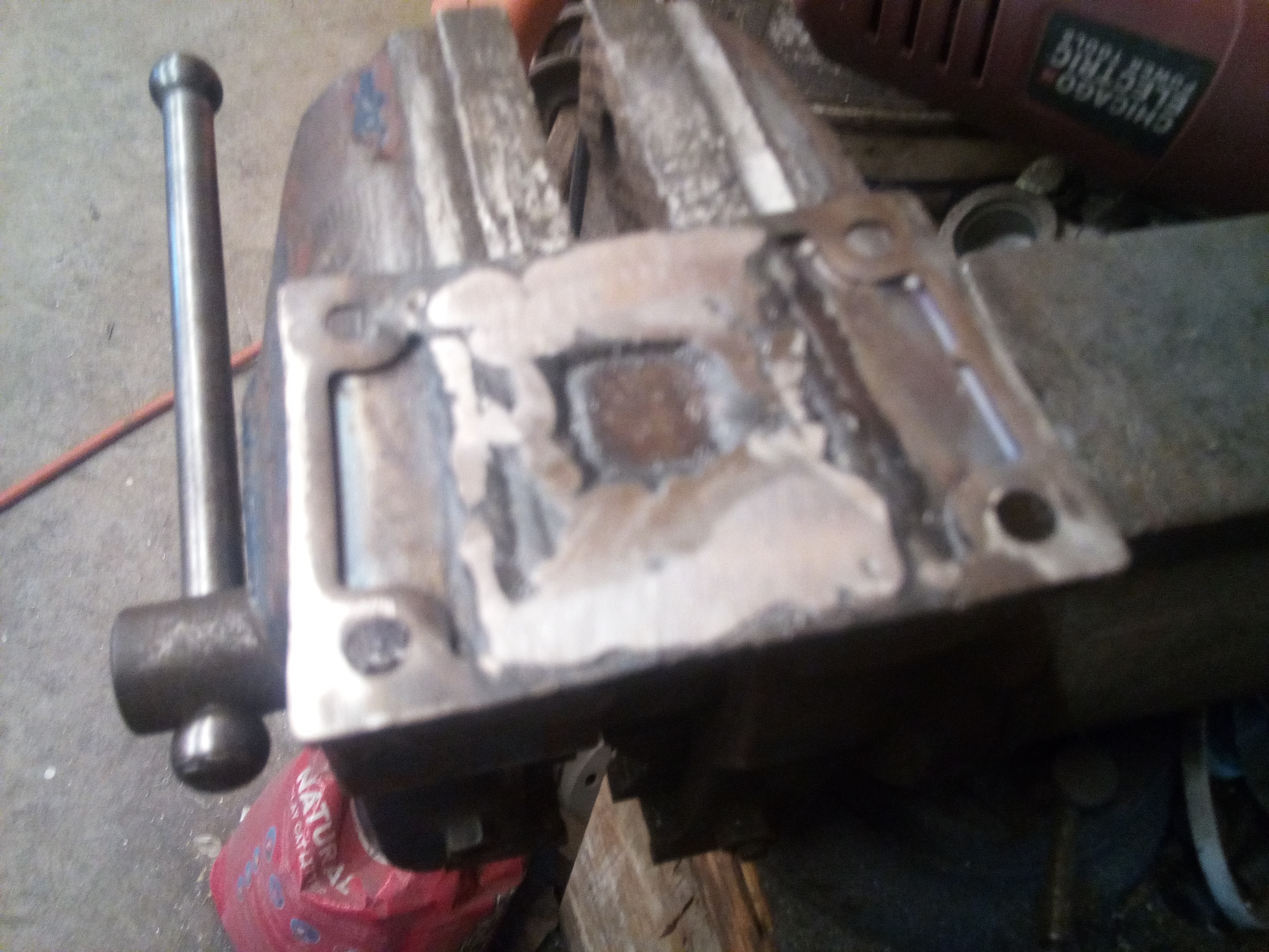
Bottom to show where the welding needed to be placed to reinforce.
Then there was the reinforcing of the wheelhouse roof, and mounting the pylon. I get a lot of questions from passers-by as to what I am doing...quite impressive from any angle.
With the arrival of the new nutsert installing tool, I got the nutserts installed in the thinner metal locations for the deck plating. In other locations, I have used either J-nuts, speed nuts, or nutplates.
J-nuts to attach the inner hawse pipes.
Nutserts for heavier use areas.
In the thicker locations I started the tedious process of piloting the holes, drilling to tap size, and hand tapping. This got old fast. Then I stumbled on to a really cool bit that "required" that I get a small cordless impact driver. It is a combination drill-tap-countersink.
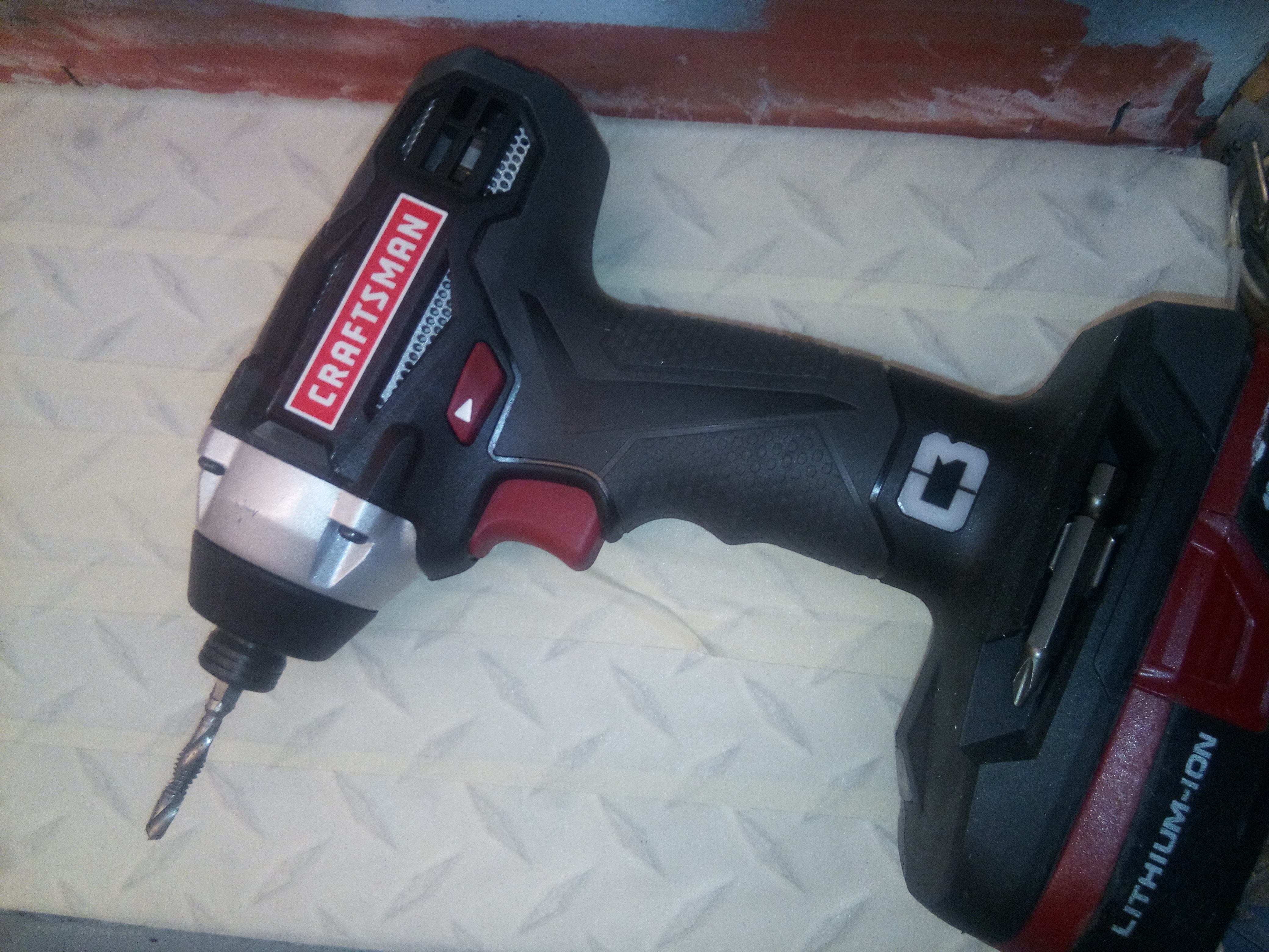
The new impact driver/drill I "had to get", with the combo drill/tap.
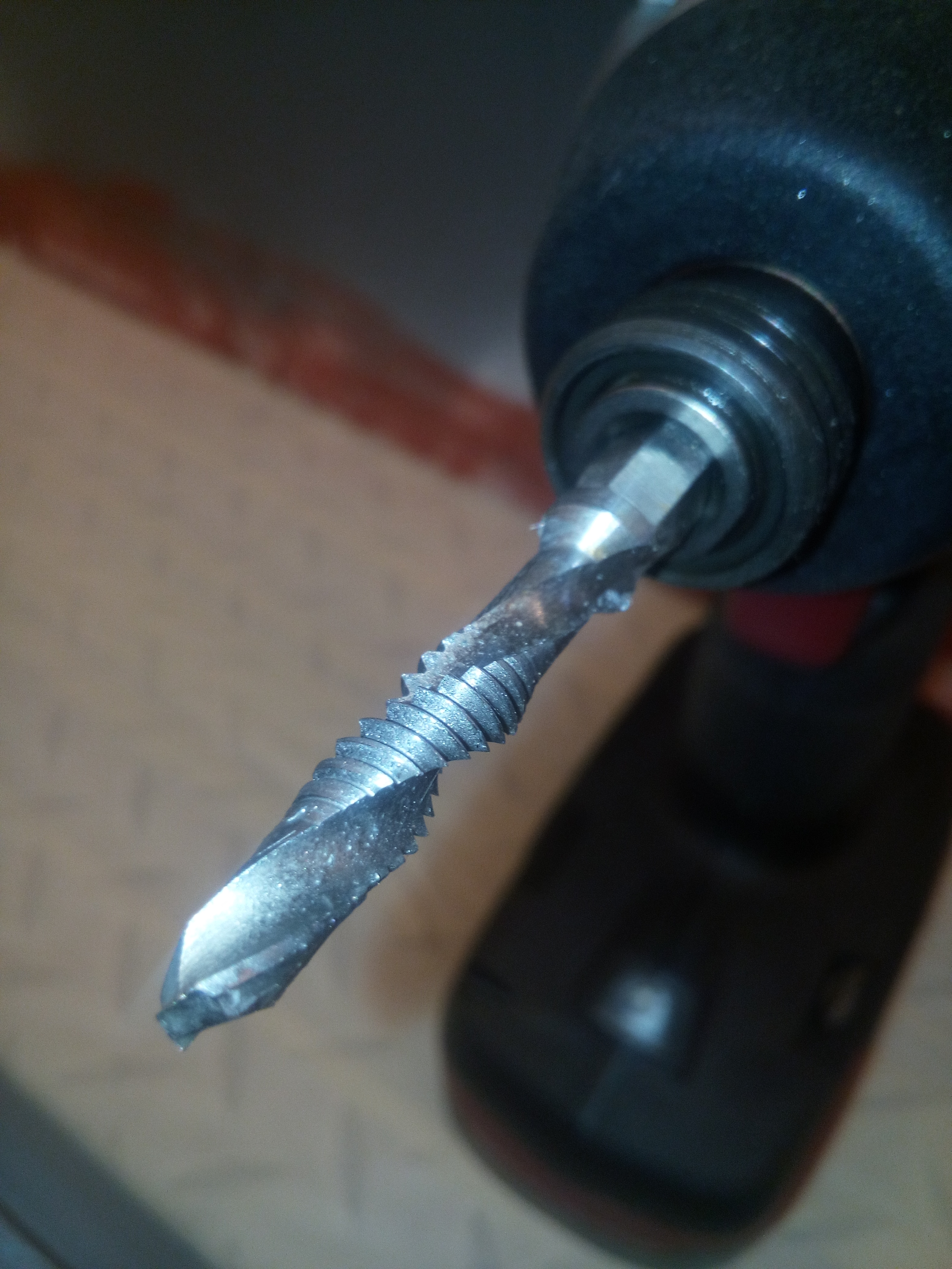
Close-up of the drill/taps. Turns three steps into one.
These are made in the common sizes, in this case, 1/4" X 20 TPI. I bought 2 in case I broke one. Hasn't happened yet. This took an all day process and turned it into a 20 minute task. Cool! I ordered several small sets in both metric and USS threads.
Then!, ... miracle of miracles, the shop that I contracted last year to make my prop duct casting plugs finally came through. Here are a couple of the printing pictures.
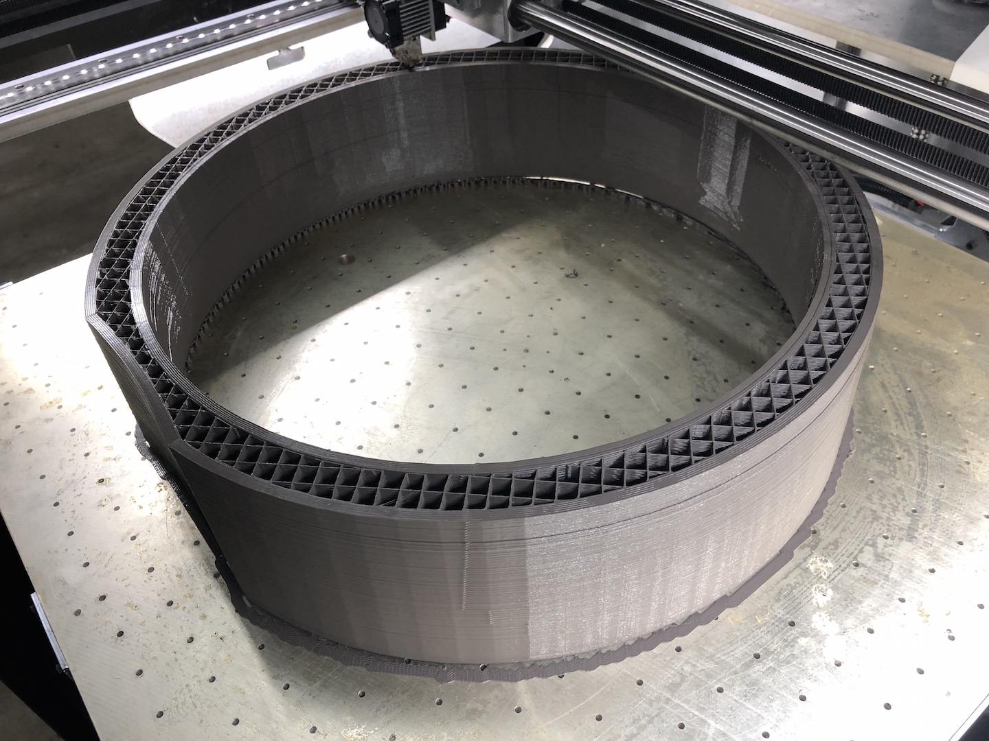
New duct printing at just over 50% printed.
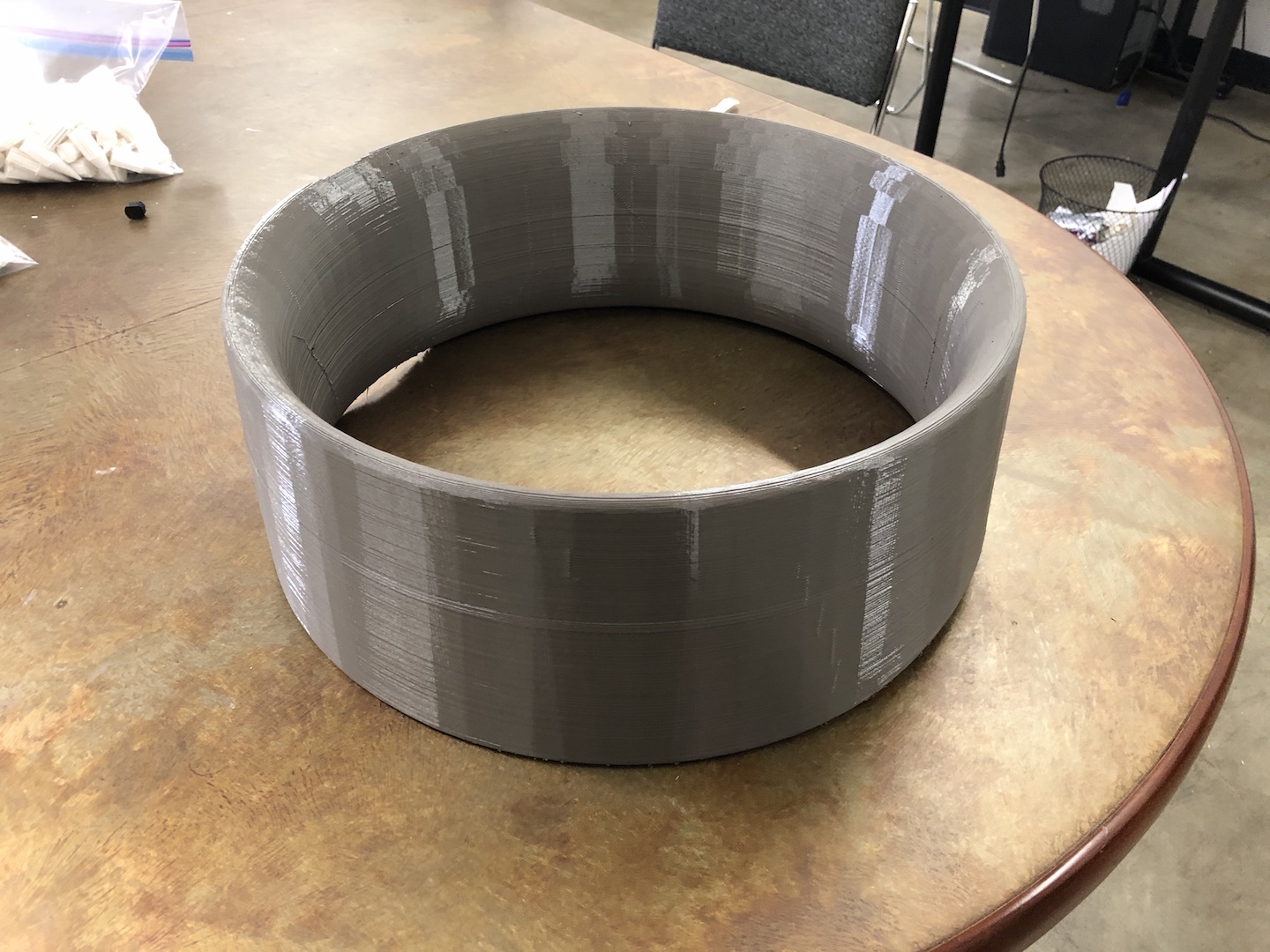
Completed printing just before shipping from Texas facility.
More on this later...
I finished making the port side deck skin, and cutting out the forward deck skin. I first made a cardboard pattern, then cut out the piece 1/8" - 1/4" larger to account for final fitting and finishing the edges. That will be finished, trimmed and edges de-burred next week I hope.
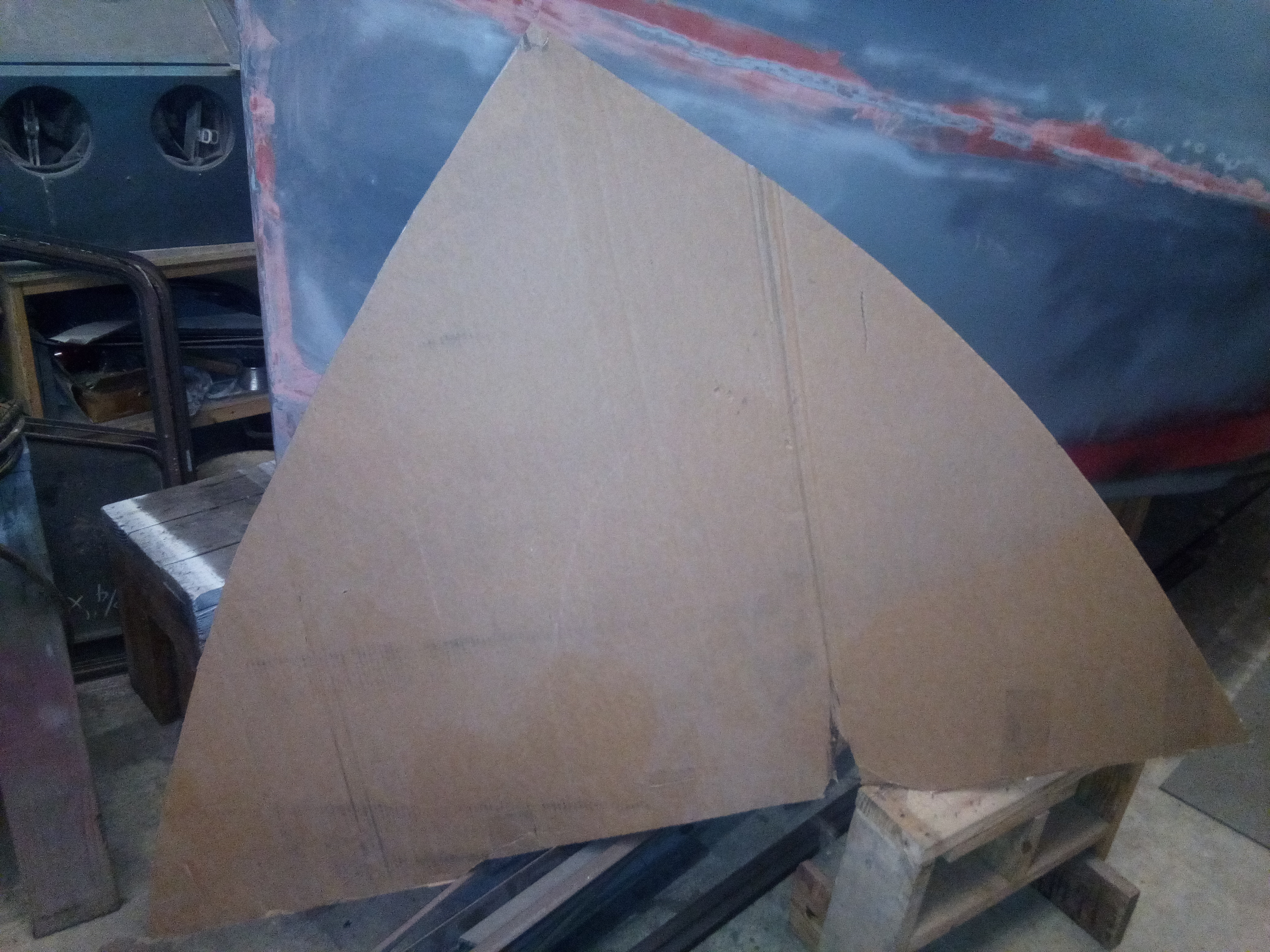
Foredeck pattern from a Refrigerator box.
Foredack plating roughed out 1/8"-1/4" oversized.
Along the way this month, I bought a pair of "dummy" batteries for final locations and wiring of the battery bays. These are monstrous batteries. They measure 5" wide, 22" long, and 13" tall. And because they are AGM construction, they can be placed upright or laid down. The reserve capacity of each is more than 2 of the group 31 batteries each one of these are replacing.
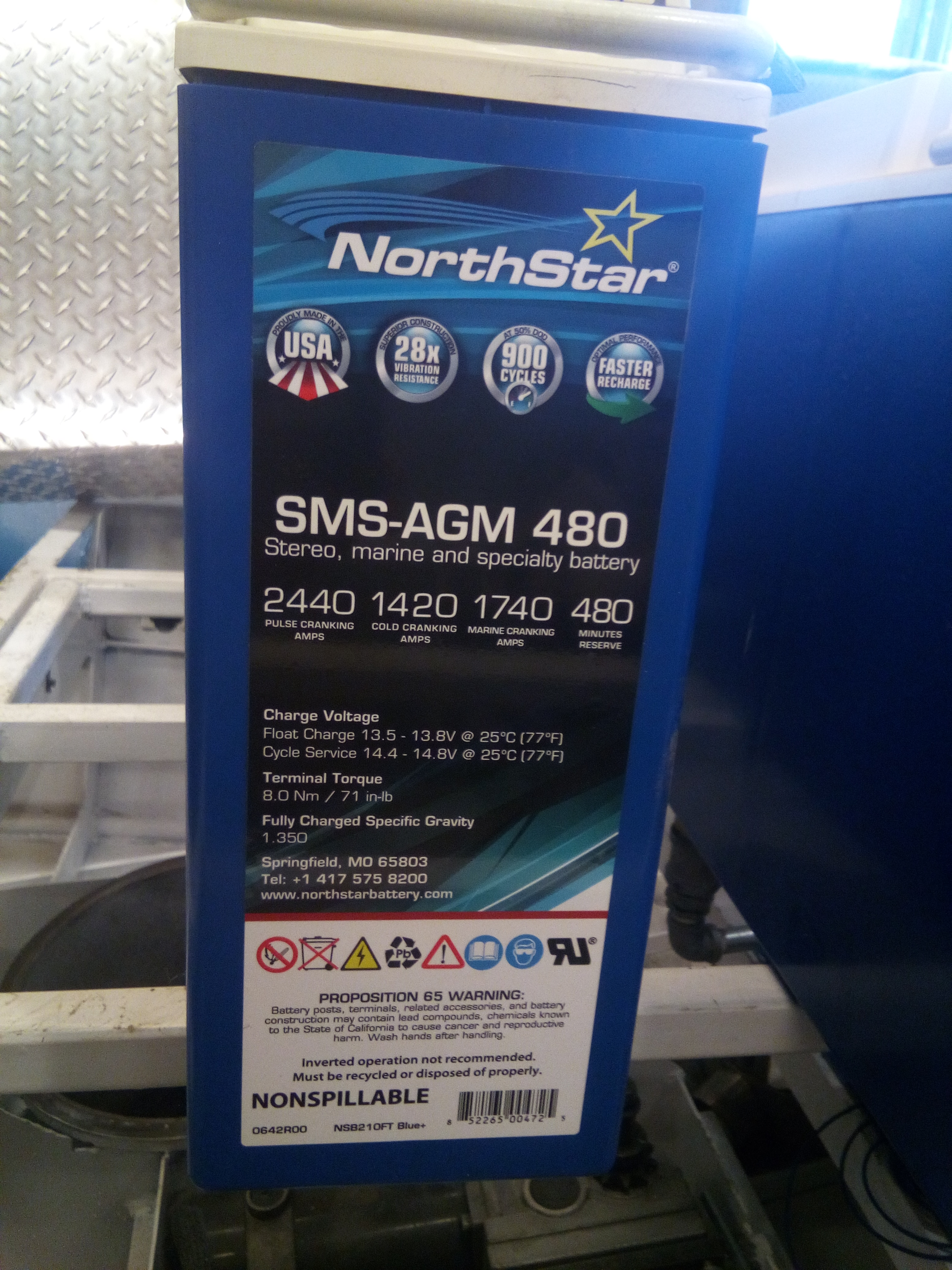
NorthStar "dummies" are just cases without guts for construction purposes. I think $50 well spent.
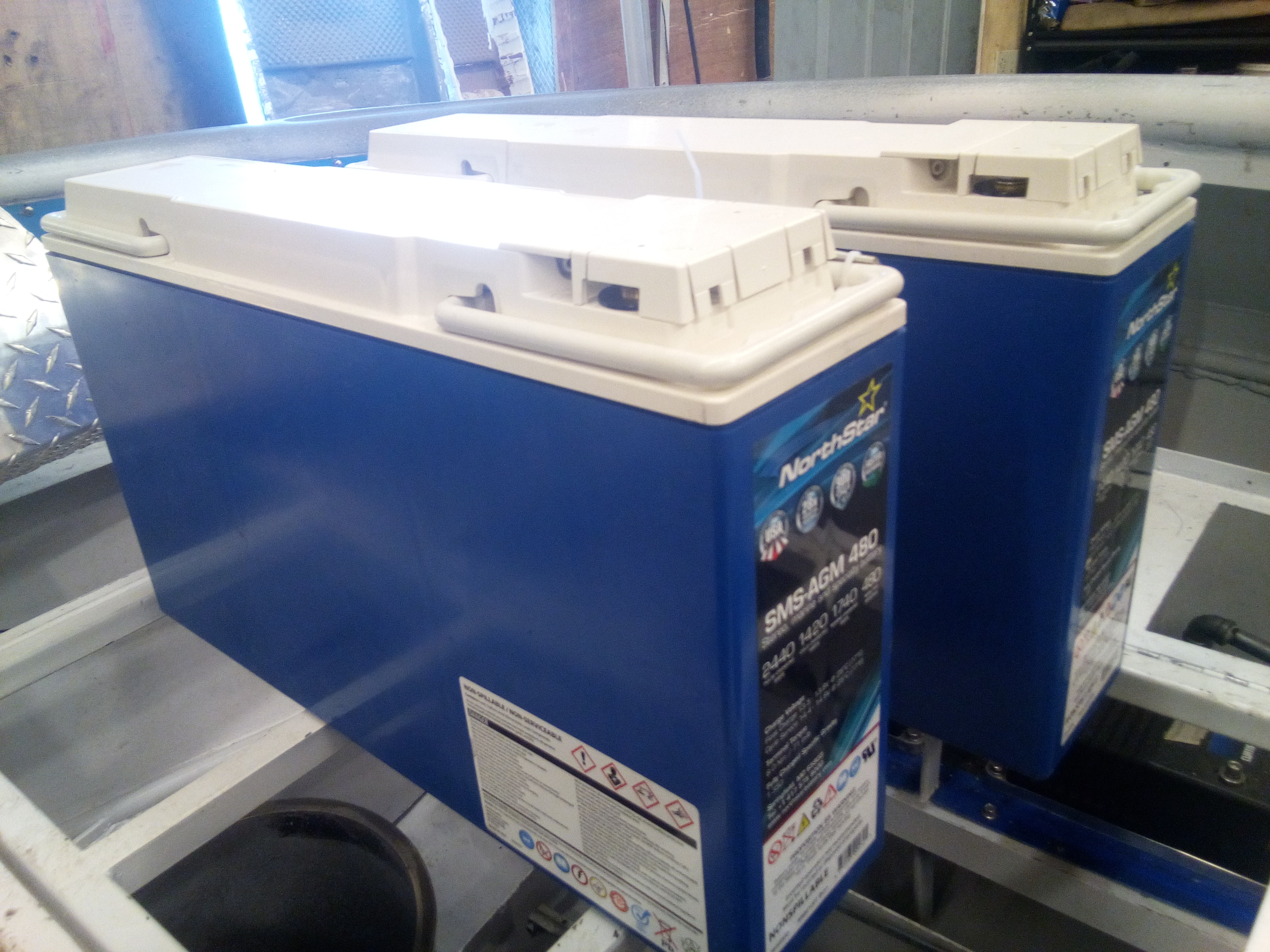
These are really dense AGM batteries, perfect for stowing in limited bilge space.
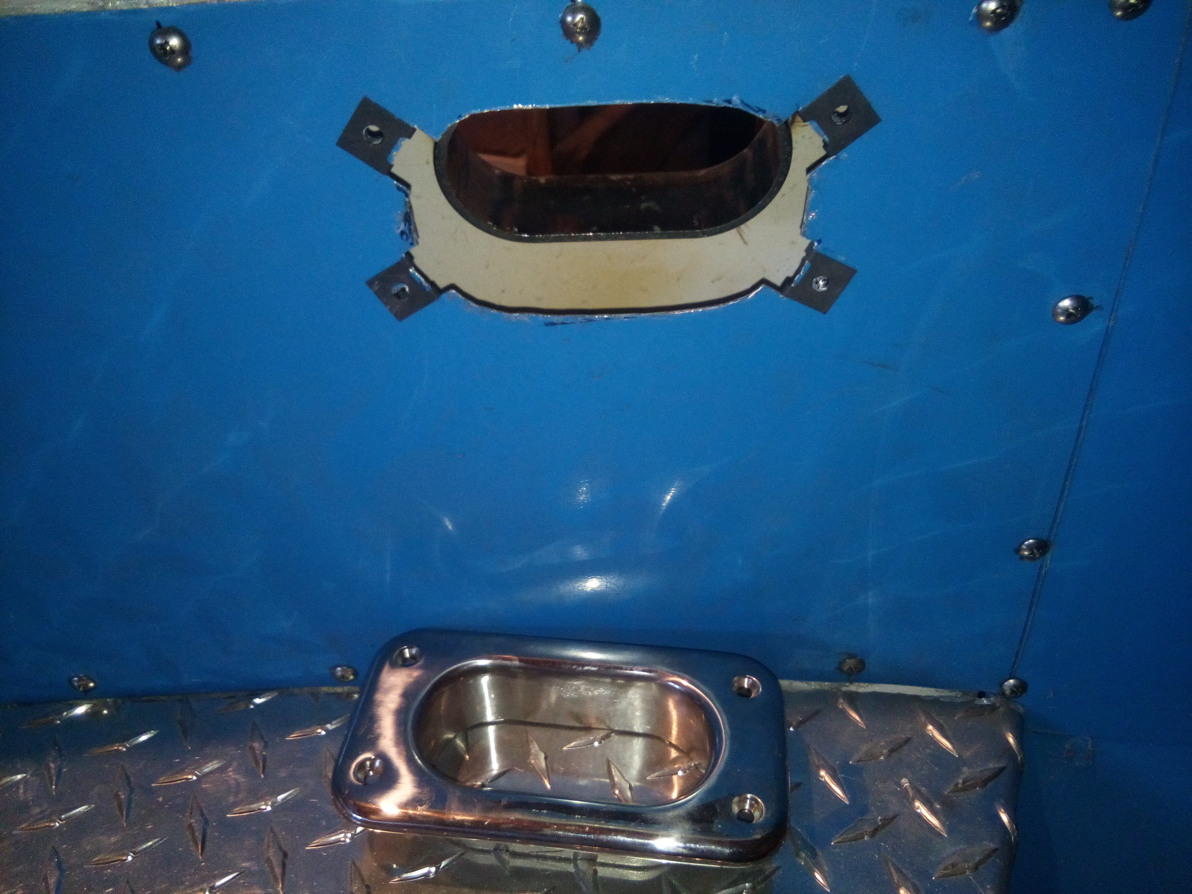
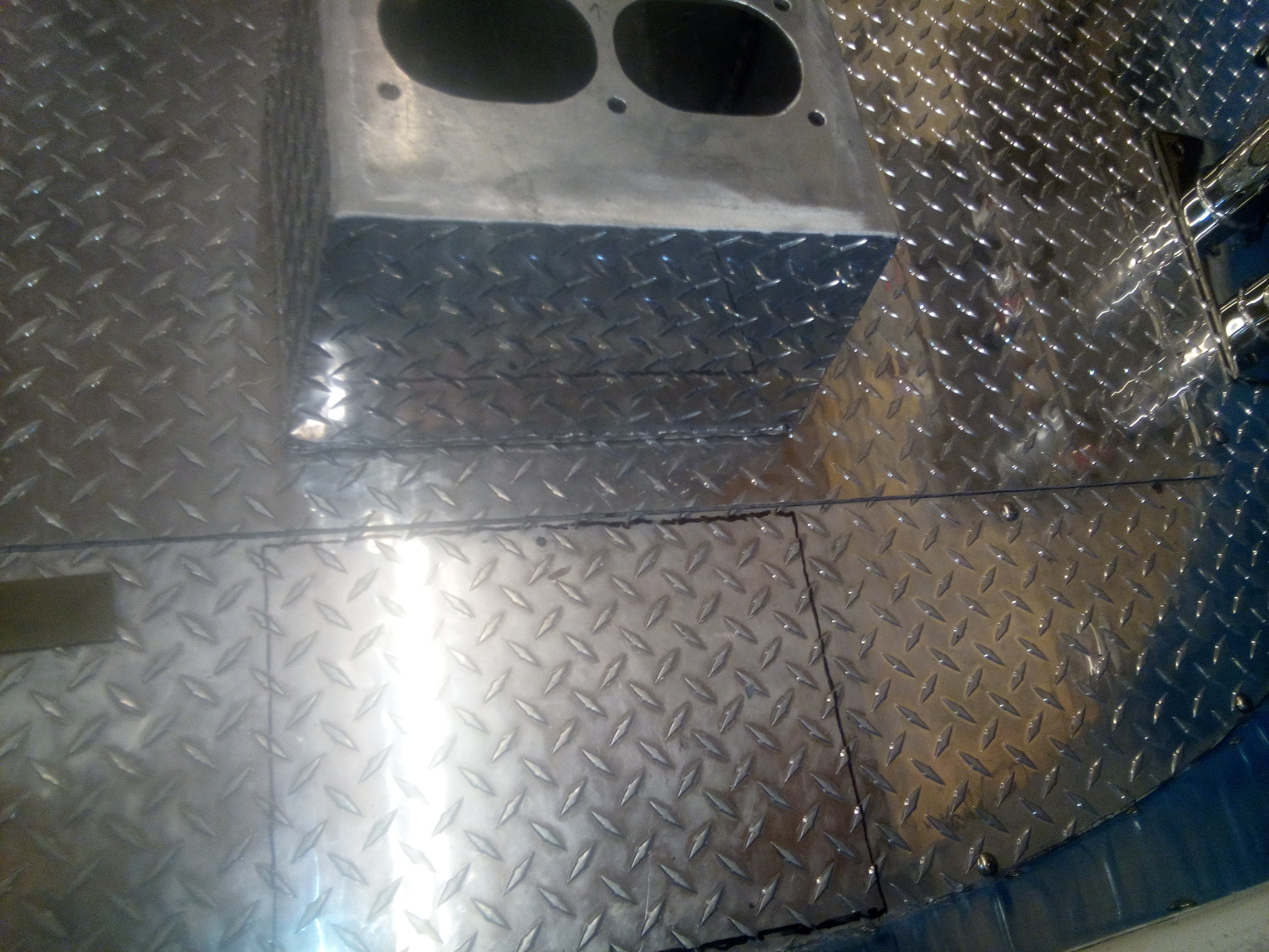
Here is a picture of one of the 2 aft through-ways that were roughed out to accept hawse pipes. Note that there is about 3" between the outer hull skin, and the inner bulkhead skin. So, the use of inner and outer hawse pipes was my answer. Then I will be making rubber boots and using silicone to glue them sealed to the hawse pipes in a couple weeks. This will satisfy the desire to keep things clean and dry below decks, ... in theory.
Inside of roughed out throughway prior to dressing, drilling, and fitting j-nuts.
OK, on back to the thrust enhancing ducts. Here are a couple pictures of the 3D printed ABS duct. The surface finish is far too rough to make a sand casting in aluminum, so some detail work has to be done. Here is the development of the final product that will be used as a plug to make a mold in casting sand to be filled with aluminum. The first picture is a close-up of the flaws in the printed part. The second picture is of the application of Lacquer spot putty to the surface just after wiping the surface with Lacquer thinner. Several coats later, and sanding to get the smooth, soft finish that will be blemish free. The last picture is of the inside surface almost to contour.
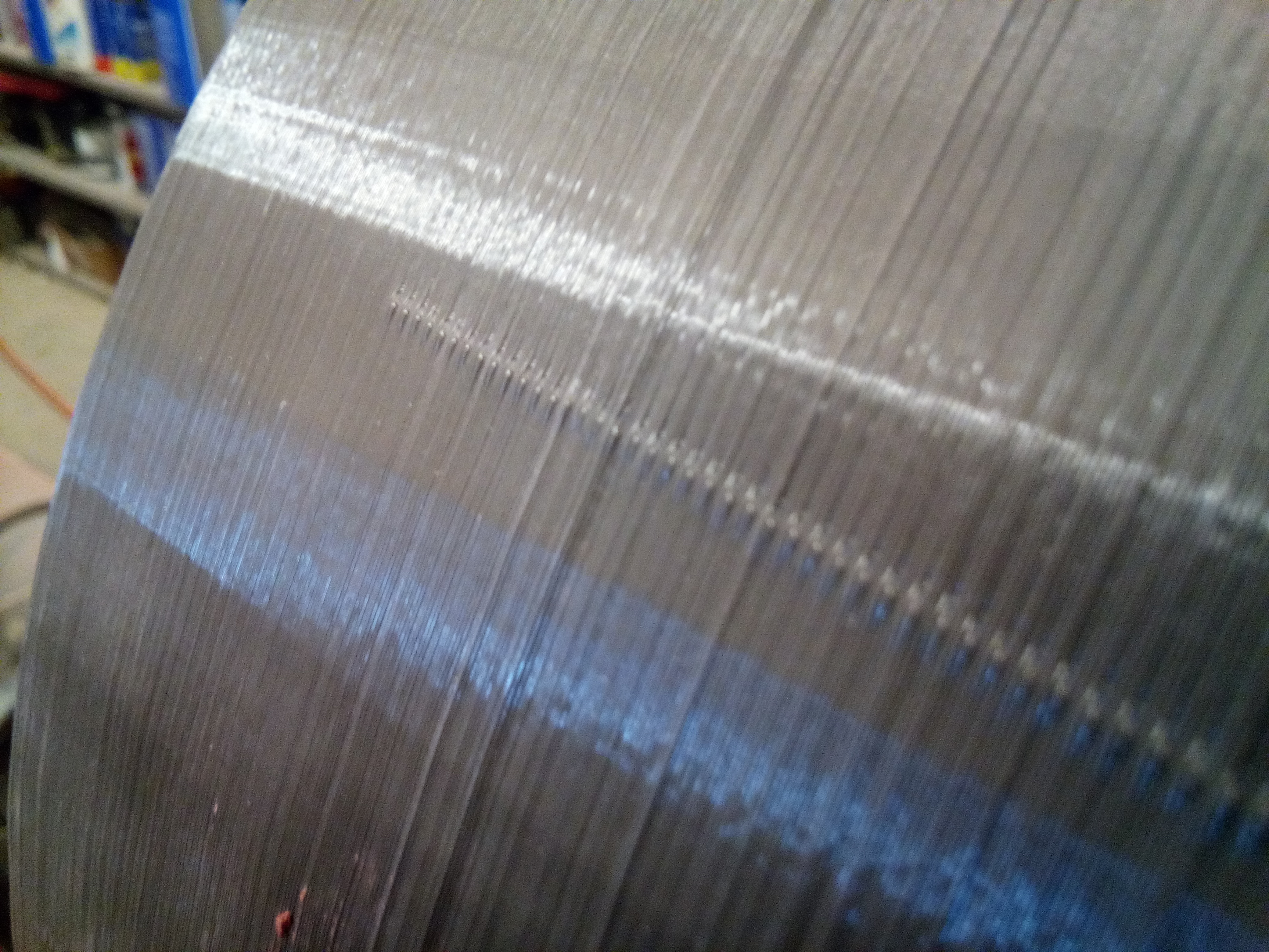
Close-up of the printing resolution. Too rough for a sand casting.
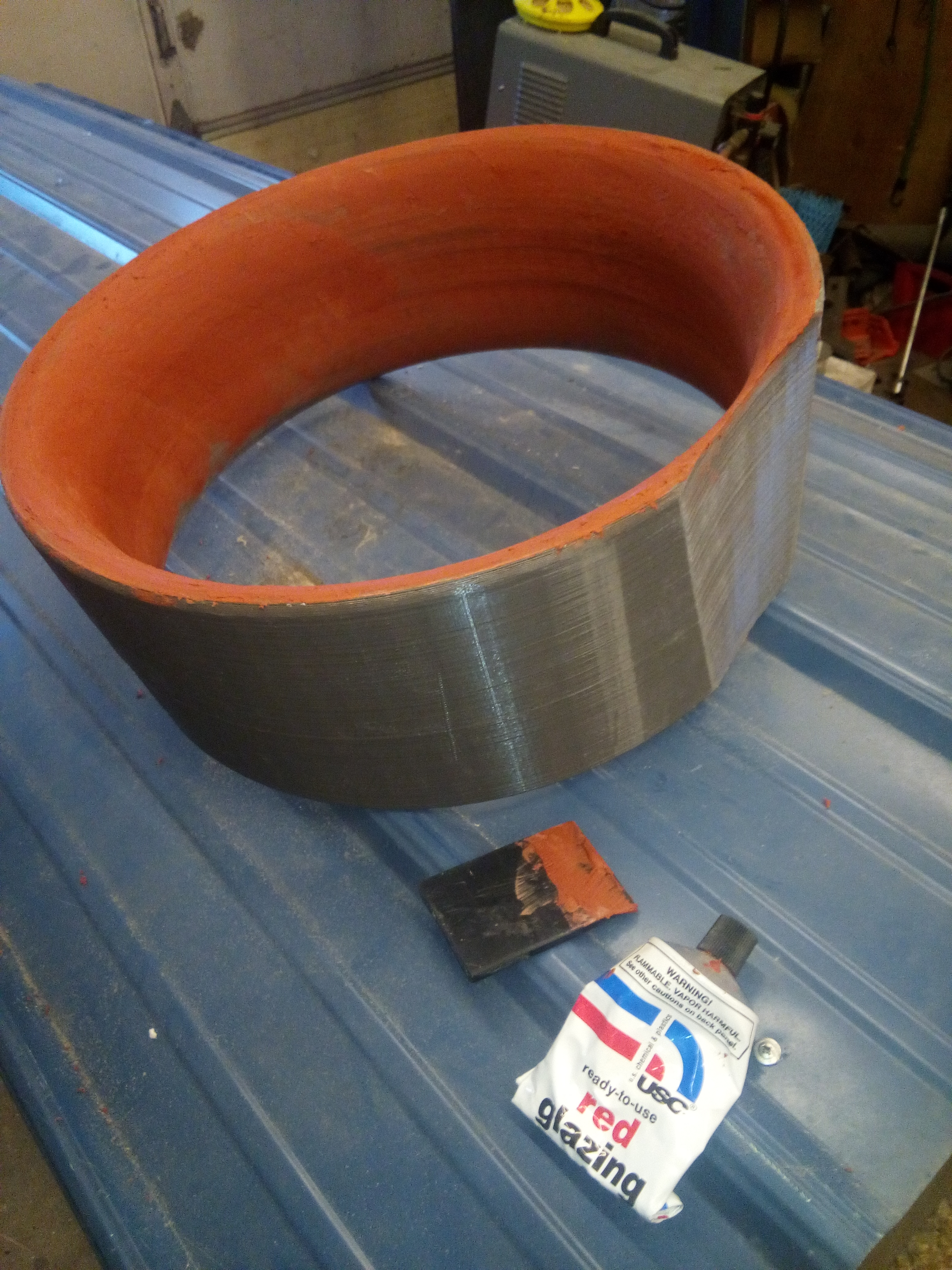
Started applying the spot putty.
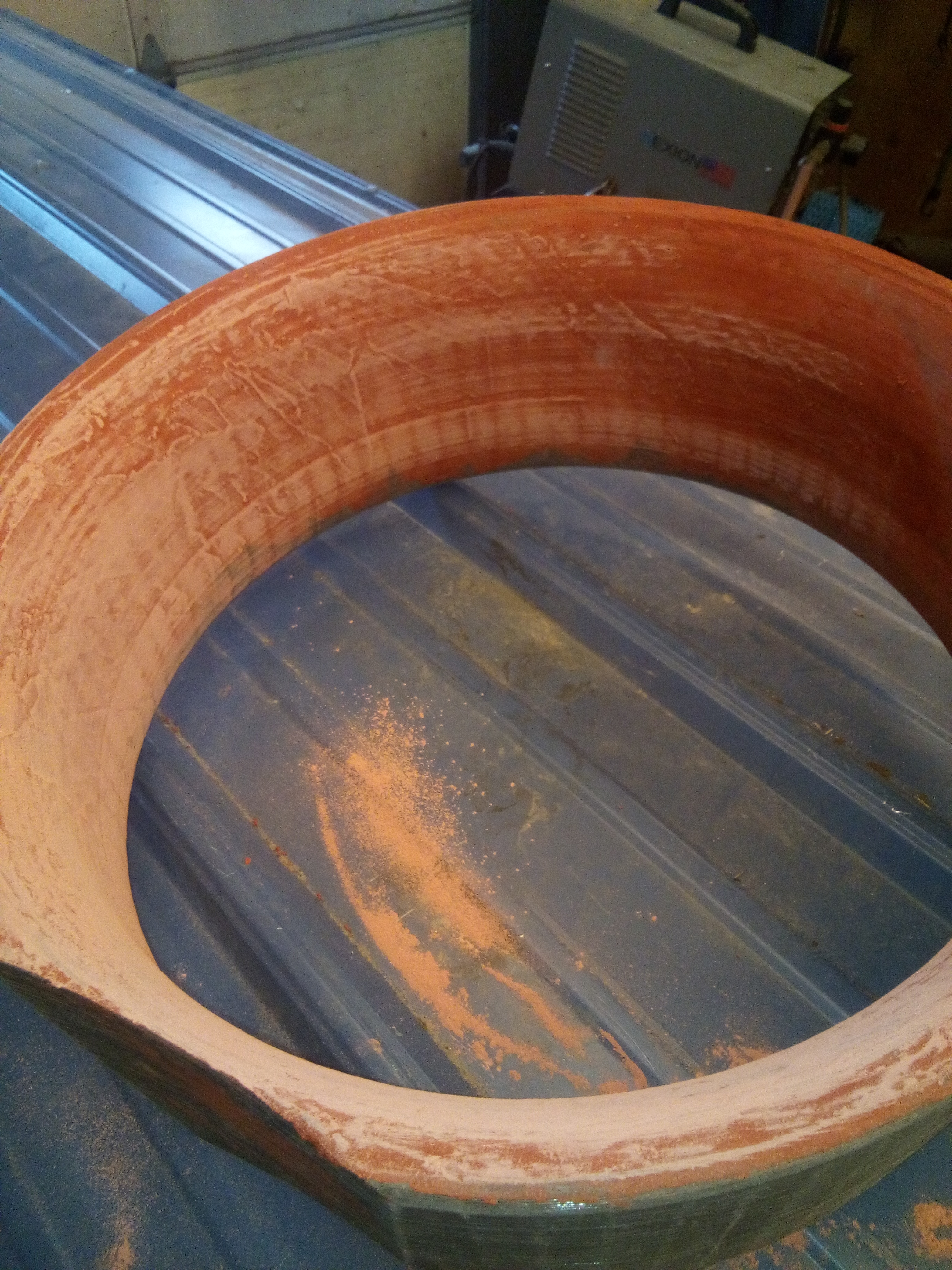
first coat sanded on the inner contours.
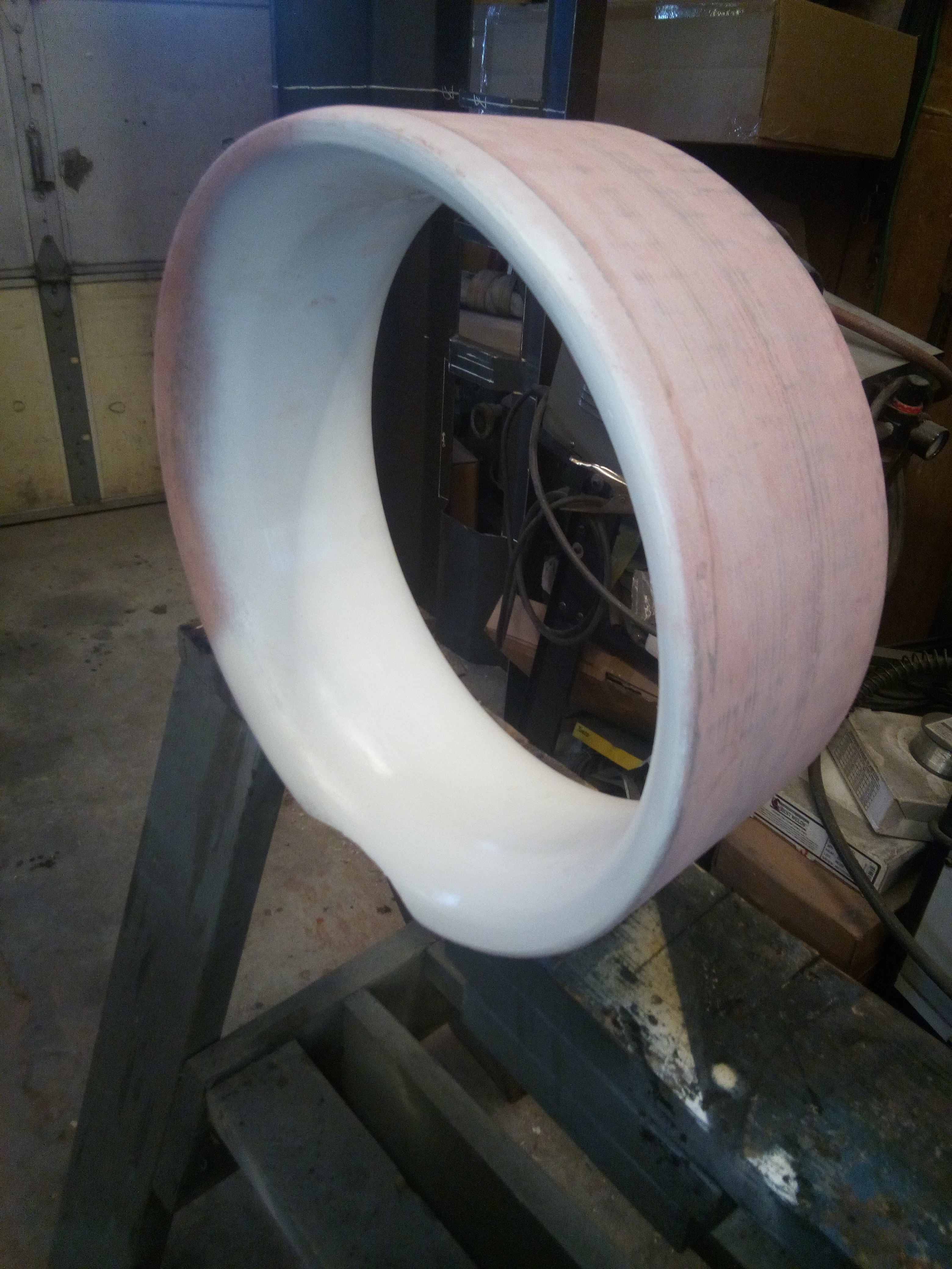
Near-finished on the interior surfaces, on to the outer surface.
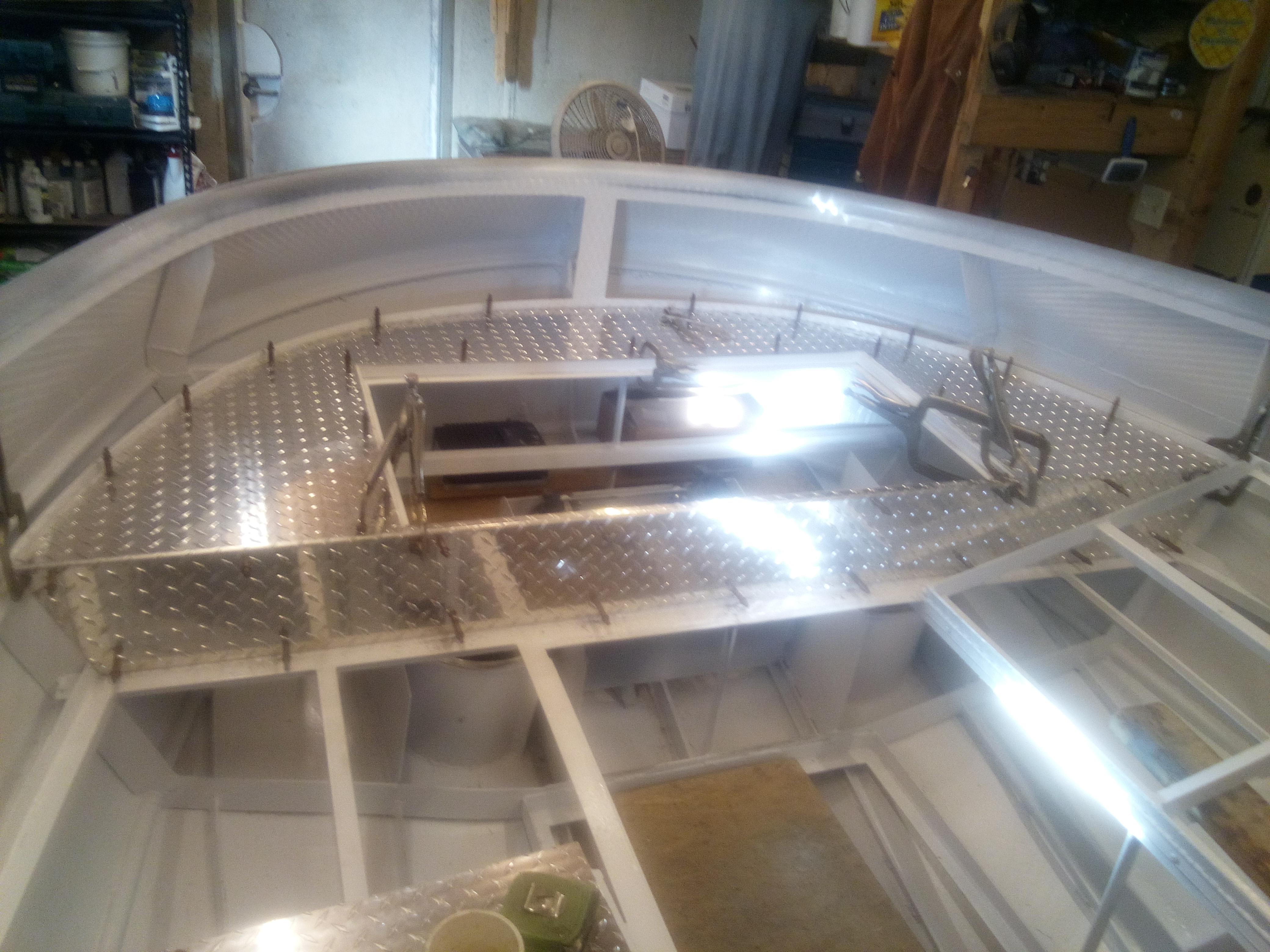
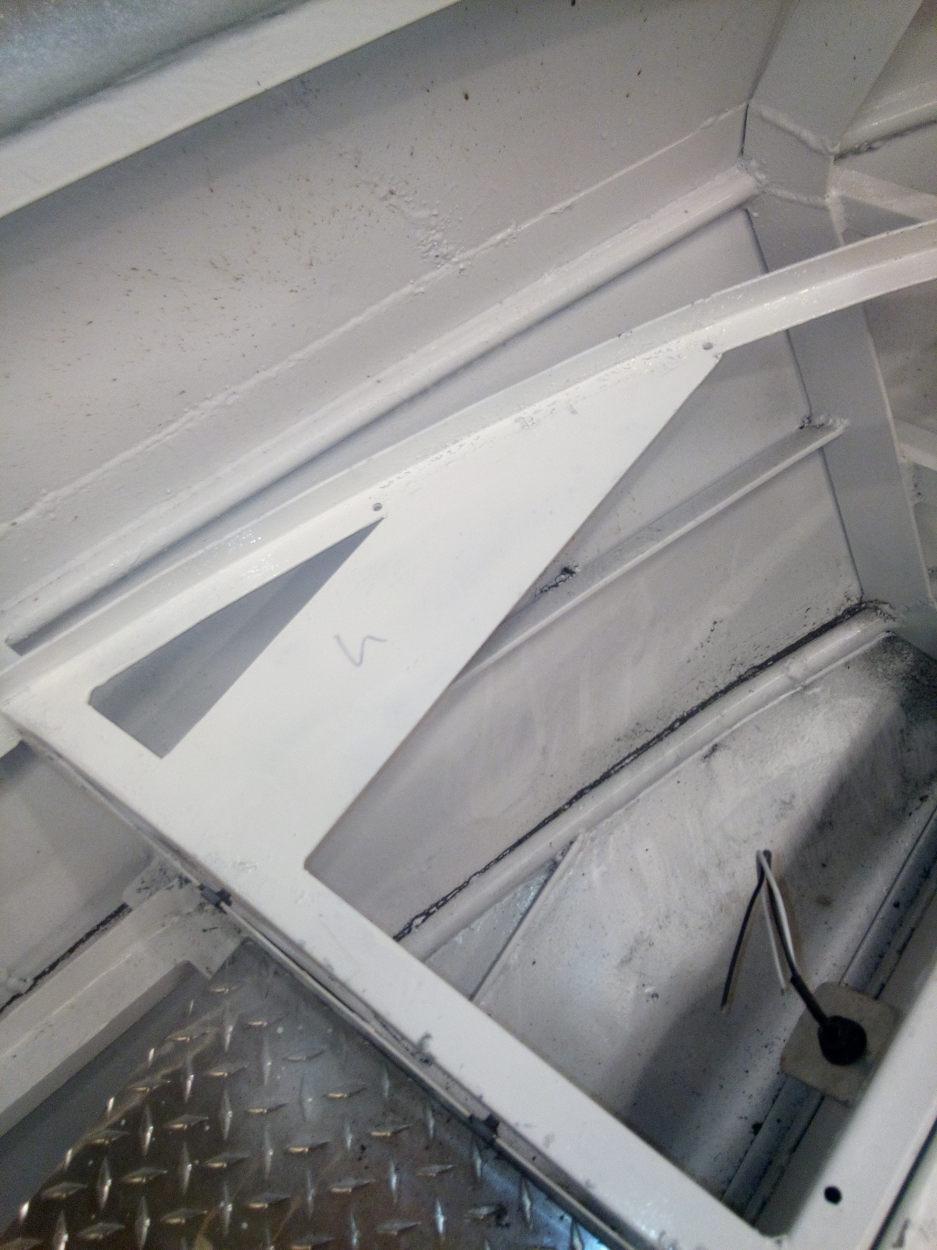
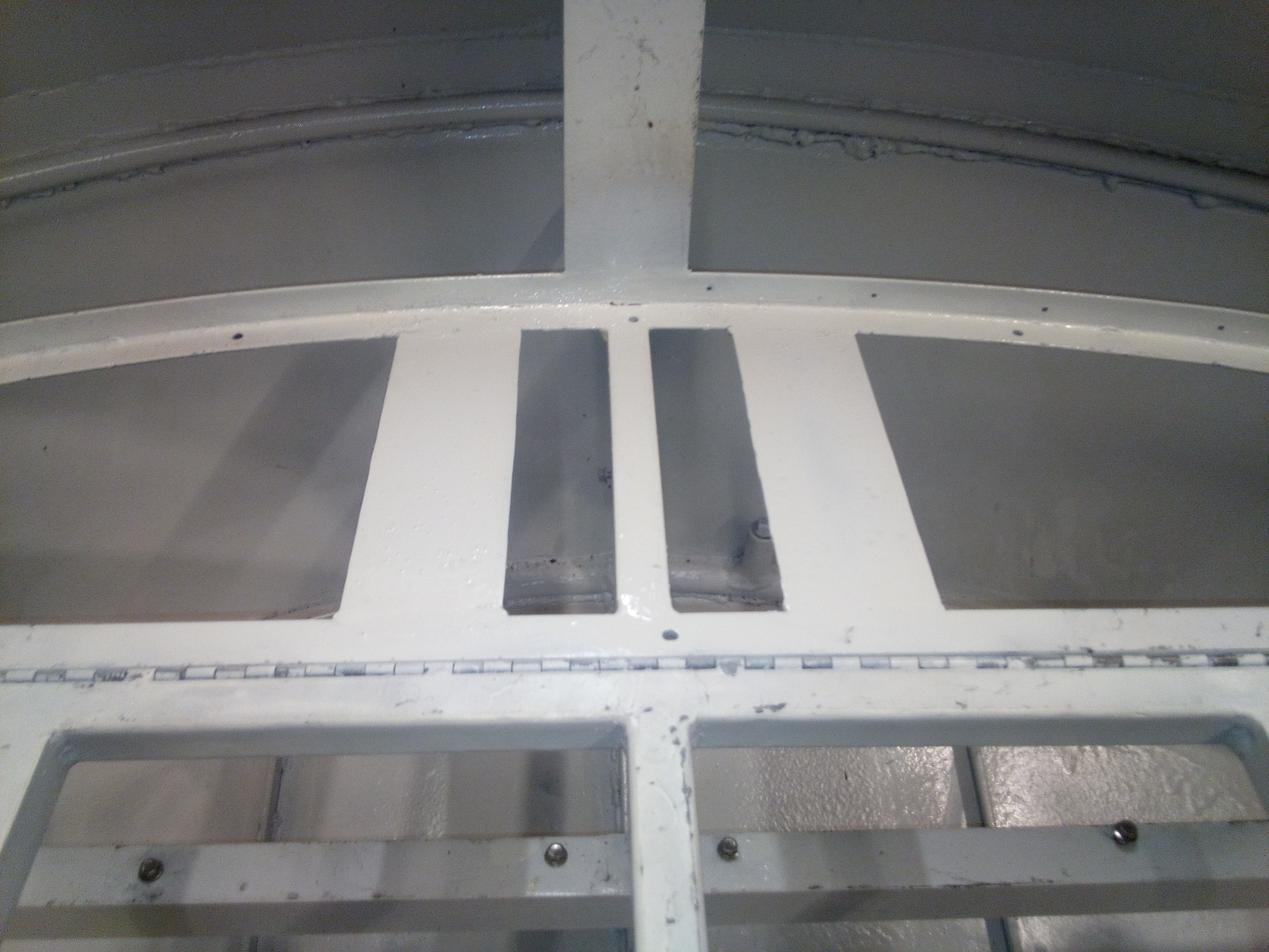
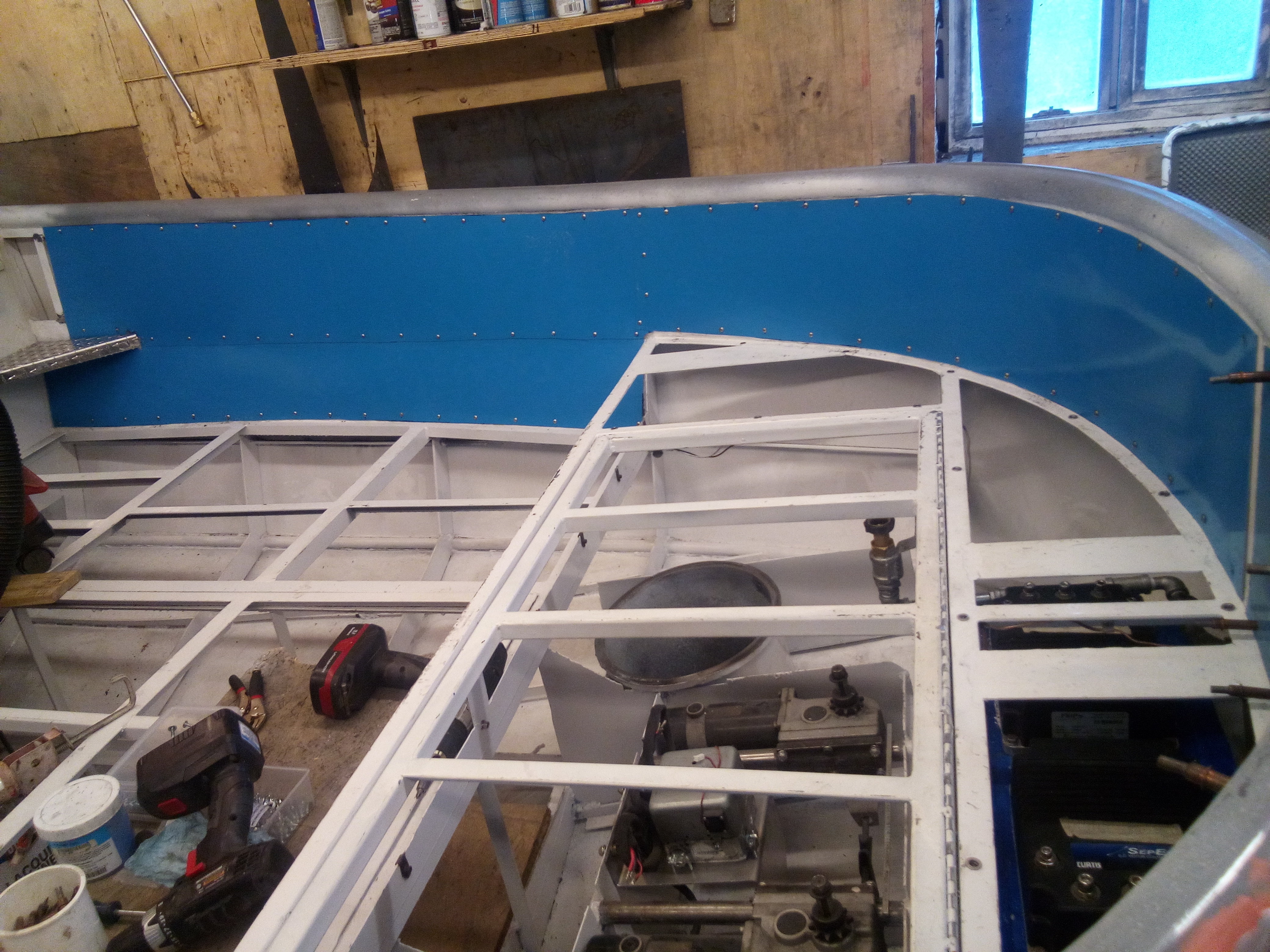
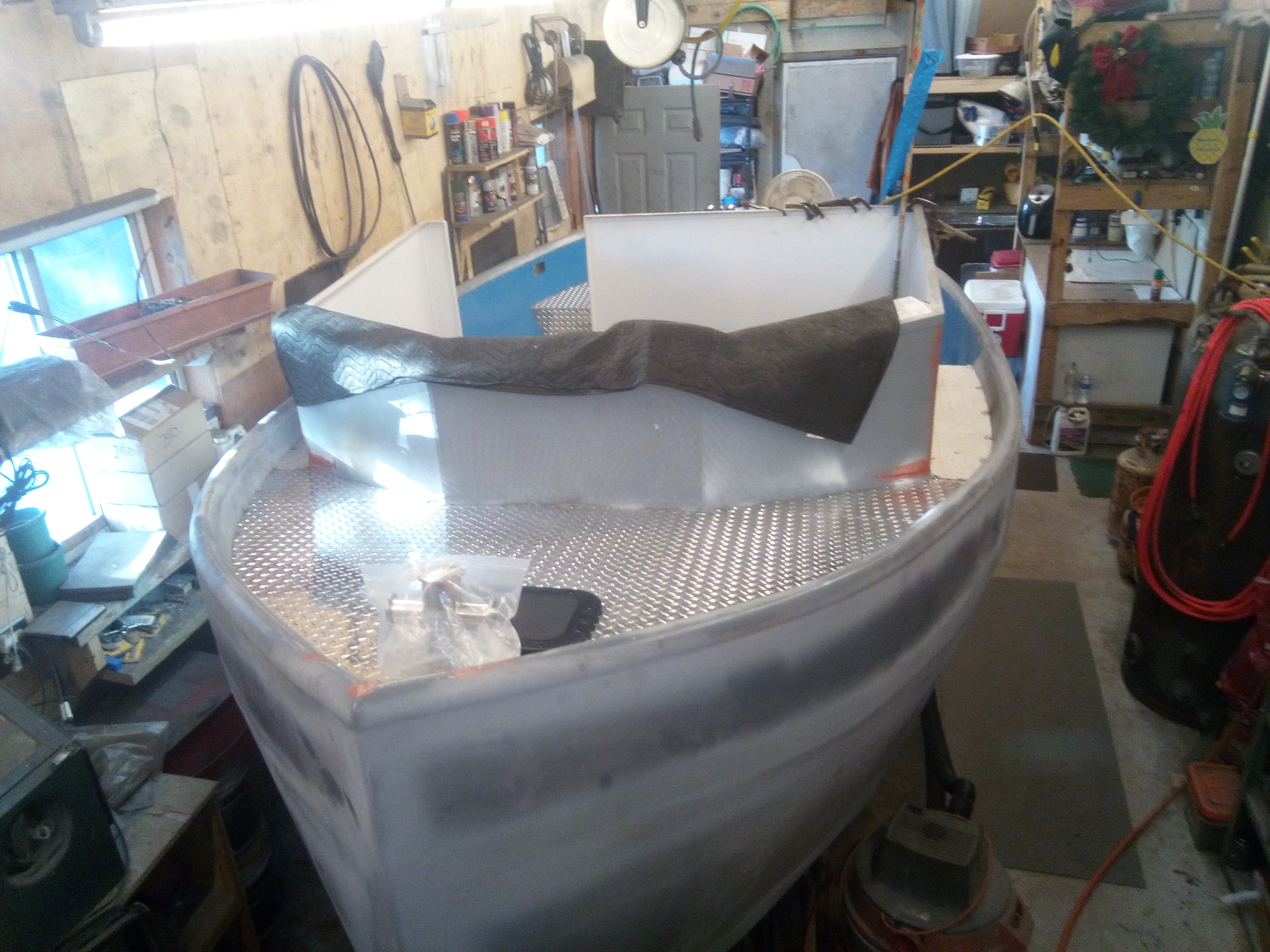
And finally, here is the shot of all the inner aft hull bulkhead skins made and screwed down. I had to stand back and admire my work. Since I did the work, I thought it a thing of beauty.
Inner bulkheads all in, waiting for the deck plating to be screwed down.
This has not been too much, but a lot of the finish work is coming together about the same time now. A couple weeks ago, I took the double bollard to Volenweider's shop for fabrication of a pedestal mount to stack the bollard just high enough to barely rise over the fantail. That is due to be finished soon.
29 June 2018 I know it does not seem like much, but there has been a lot of planning and preparing to get these last parts installed. I would hate to cover an area, just to have to undo all the sealing and work, so I can install something below decks...
Since the last installment, I have finished smoothing up the ABS printed duct, and delivered it to the foundry in Kansas City. After careful research and consideration for time, distance, cost and quality of product, I chose to drive the 280+ miles to see Bill at Ace Foundry, and hand deliver the duct to him.
I got the aft pedestal made and installed, as well as mounting the aft twin-bitt (bollard?). I've had several discussions on what it is called. Would hate to call it the wrong thing.
Cutting access holes for mounting.
In place ready for bitt to be installed.
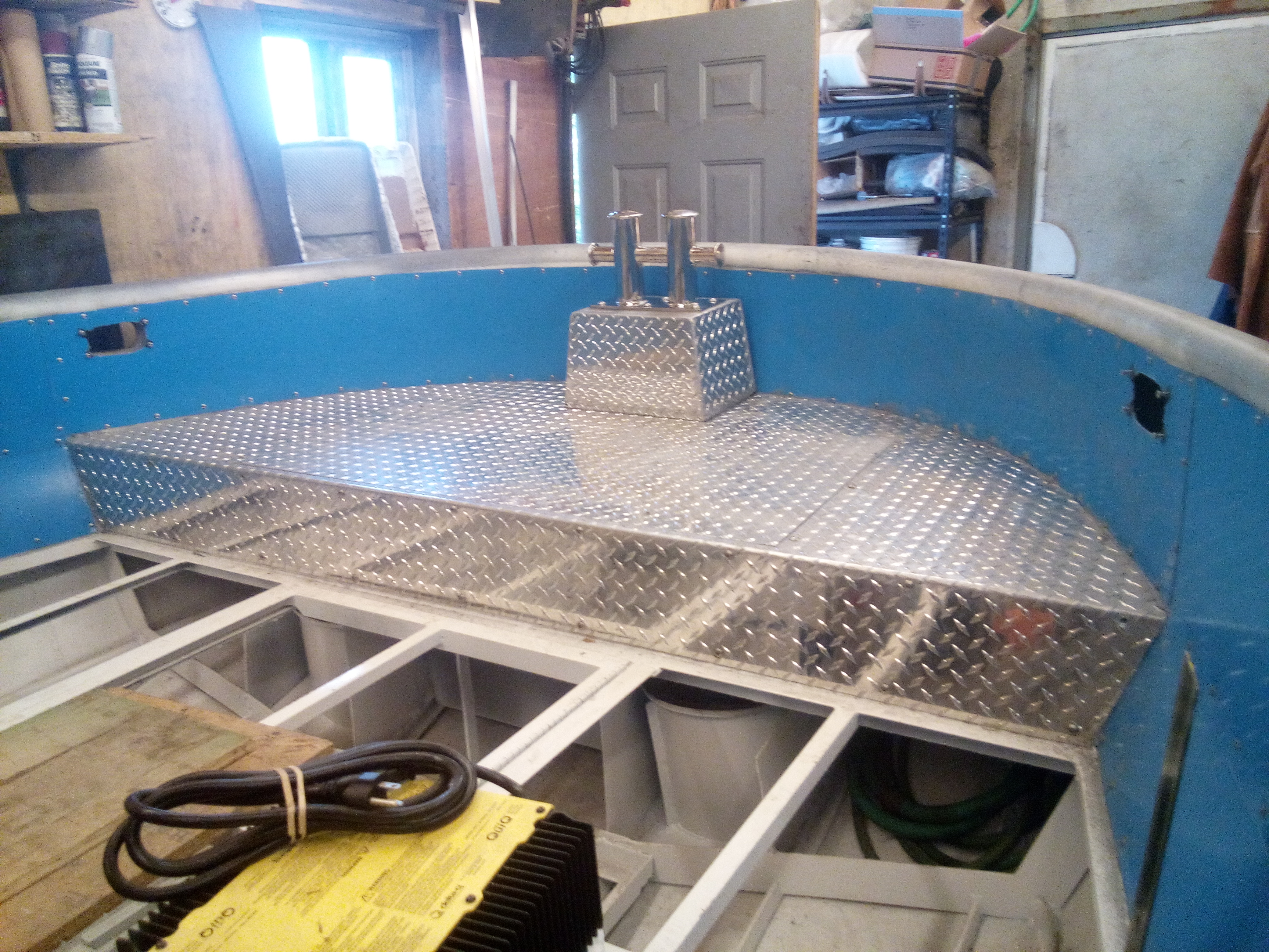
Look Ma! I dun it all by ma self! Ain't it purdy?
I also got the fore-deck plating extensions welded, smoothed, and screwed down. Then I cut the access-way for the rope locker hatch, and installed the forward bitt. The area where the bit mounted had to have the tread pattern removed so the bitt would sit flat and tight to the deck plate.
Fore-deck going down.
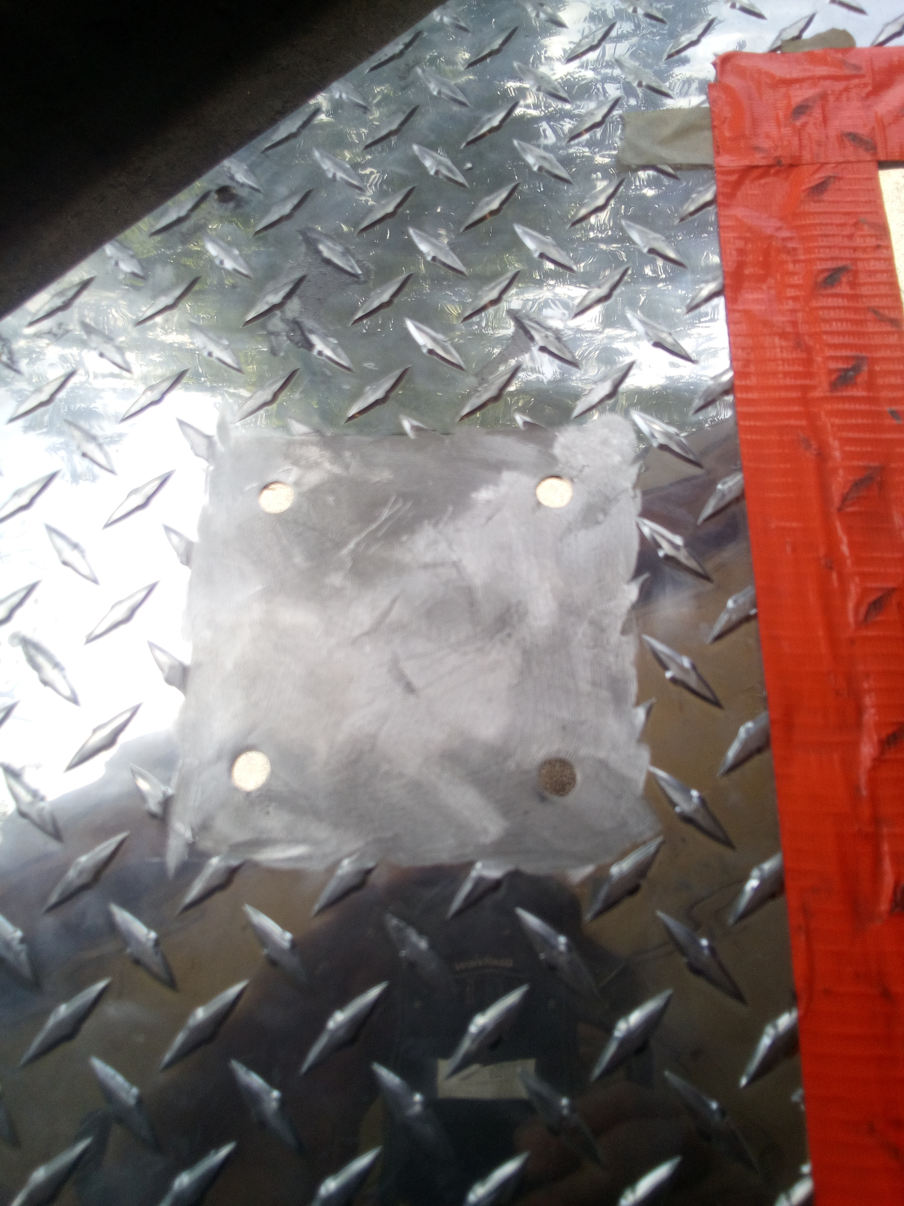
Had to grind the "tread" away so the forward bitt would set down tight to the deck.
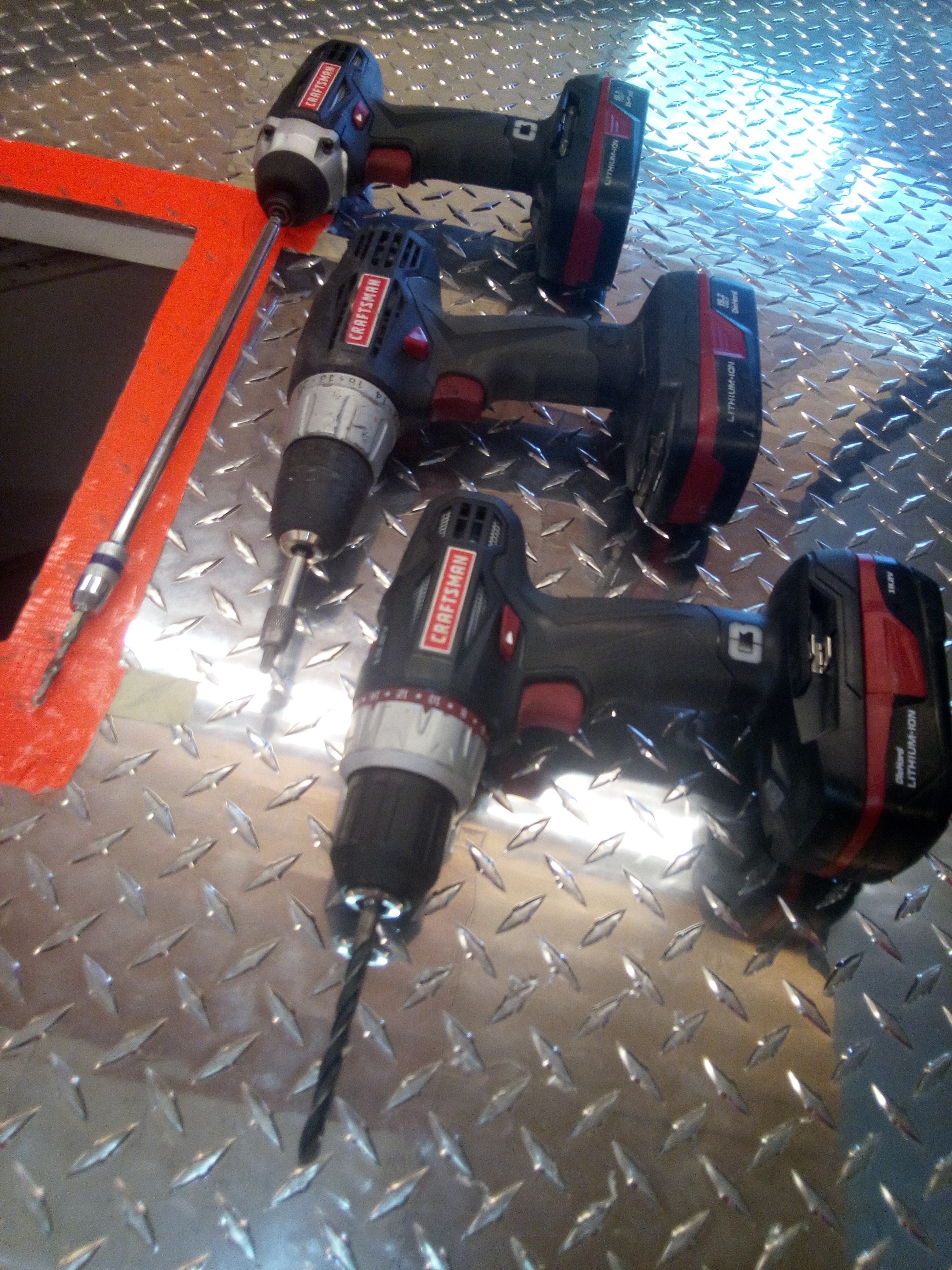
When doing the decks, I found having several drills/drivers was a must.
Then I finished fitting and screwed down the gunwales. Might I mention, the D-Taps have been a real time and materials-count saver. I can't say enough good about this one little bit.
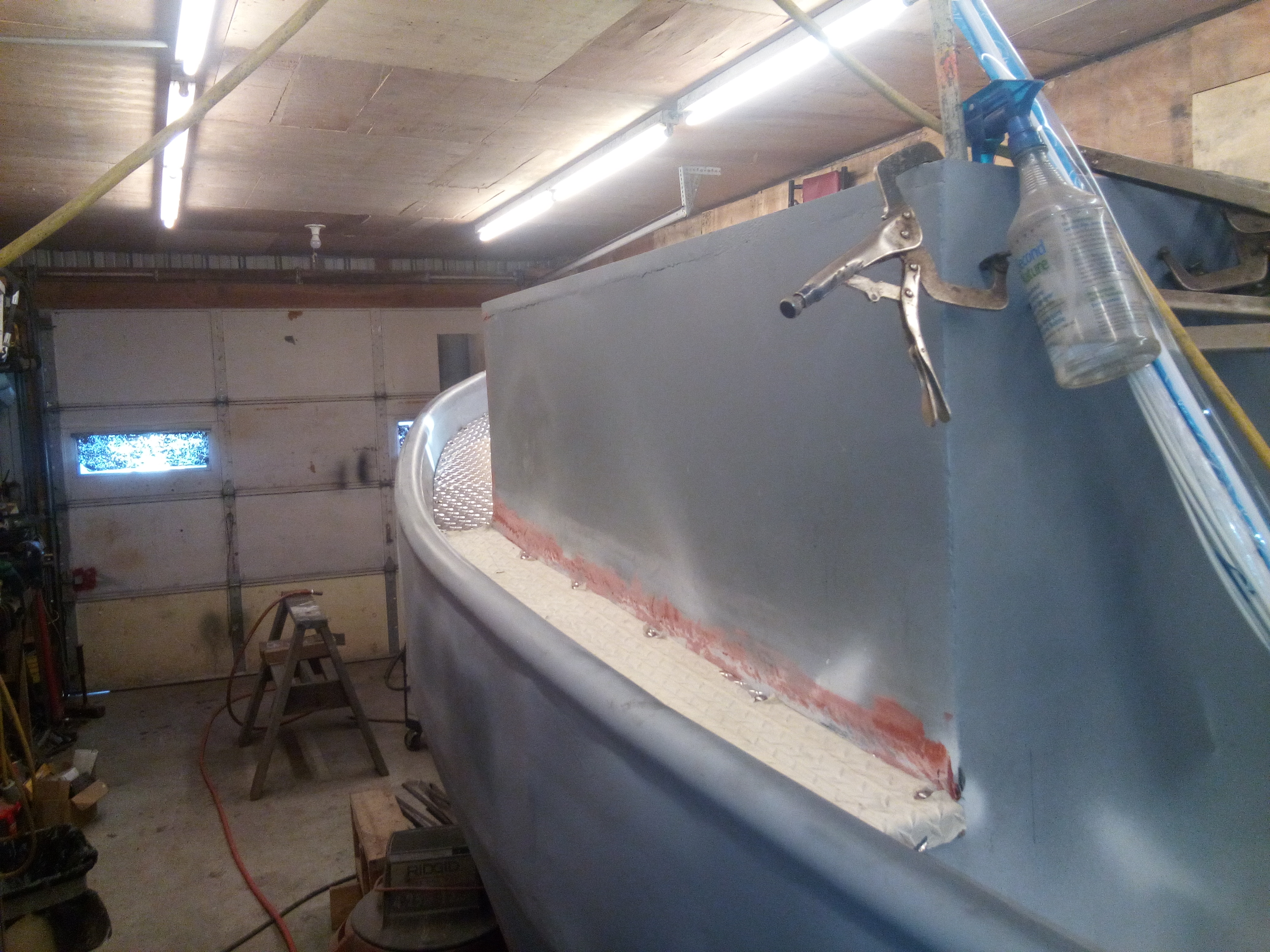
Gunwales "glued -N-screwed."
The only decking left to make and install, is the main deck aft of the wheelhouse and forward of the raised fantail deck. I am still waiting on the twin gensets to be ordered and be modified before main decking goes down.
Waiting for the gensets...
Had to take a short break from the build to build a new septic system for the farm... That wasn't cheap...
29th - After selling a car I wasn't using, I ordered the two 4400 Watt portable generators. Not diesel as I had wanted, but convertible to DC with a pair of rectifiers. More on that when they arrive after the 11th of July.
More soon... ################# ..